I have posted about this in other threads, but I have wrapped up this project, so it has come time to lay my cards on the table so to speak. Nearly two years ago I purchased a used Bridgeport clone with the intention of performing a CNC conversion. I got it up and running in a very basic way within a few months but the X and Y axes were still running the stock acme screws. Earlier this year I started a project to replace the stock screws with ballscrews, mainly to reduce backlash. Rather than going with an off the shelf kit (which I wasn't sure would work), decided to machine everything myself. I purchased some screw stock from McMaster and some cheap ballnuts. The cost was low enough that I figured if I screwed up (haha) that I wouldn't be out much $$, and if it worked, I would have saved about a thousand bucks and gained a fair amount of experience. I'm happy to say things worked out well. What follows will be a brief walkthrough of the parts involved. I didn't take many "action" shots unfortunately.
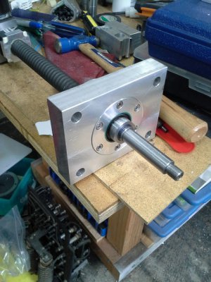
The first part I worked on was the Y axis mount. This started life as a large chunk of 6061 I had sitting around. I roughed out the shape on the mill and finished the bearing bores on the lathe and got a decent (medium) press fit. The bearings were open, so the mount was designed for double lip seals on both sides. The hole assembly was packed with grease and the retainer on the front holds the whole thing together. Here is a view of the whole thing assembled, with the already machined Y axis screw in place.
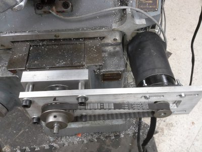
Here it is installed on the machine. The motor mounts are the same ones I have been using since I started, just 1/2" 6061.
After gaining a little confidence with the Y axis, I purchased a 5 foot section of screw stock and 2 more ballnuts for the Y axis. I also purchased a big chunk of hot rolled steel and some DOM tubing for the yoke. The original yoke on the machine used bronze nuts, and was not going to accept the ballnuts, so I had to fabricate a new one. I did this in 3 sections, 2 large pieces made from the HRS, connected with a piece DOM tubing using my MIG welder.
Here you can see the completed yoke from the top side. As you can see, it is a pretty simple design. The "bulge" in the middle is there to acomidate the pre-load nut. More about that later. I am using square ballnuts, so the channel is square, and the ballnuts just slide right in. A flange attached to the ballnuts screws into the yoke.
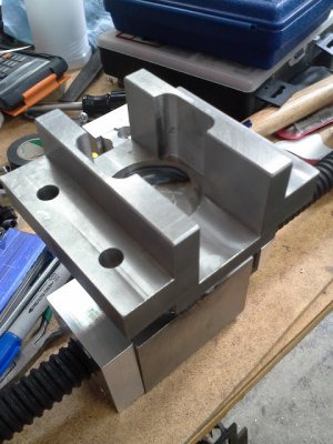
Here is a test fit with the ballnuts and the yoke. The large white piece is the preload nut.
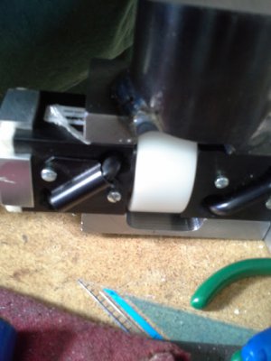
The yoke is installed way down in the belly of the beast. It requires that the table be removed and both the X and Y screws. I got very good at removing the table. I think I had it down to about 15 minutes. Each time I needed to take measurements, or test for fit, I had to tear things apart.
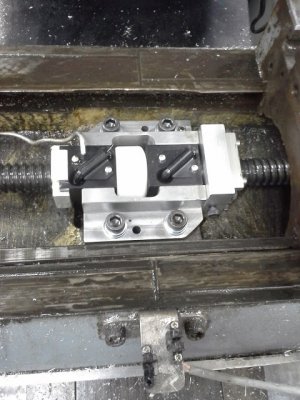
Here is a shot with the X axis nut installed as well. You may notice that 2 of the corners are clipped off. Well, as it happens, the yoke has to be installed rotated 90degrees, fed down into the cavity, and then rotated 90degrees to the final position. I didn't really test this until final assembly and it wouldn't go. I had to pull it back out, dog-ear the corners with a hacksaw and files, and try again. Looks almost like I planned it. In this shot you can also see the felt wipers and their retainers. These are just 3/16" soft white felt with holes cut slightly undersized for the screw minor diameter. The felt is soft enough to conform to the screw, and makes a really nice seal. The nuts are packed with the same grease as the ballscrew supports. Rather than purchase pre-loaded ballnuts from the manufacturer for an obscene price, I purchased to non-preloaded nuts and made my own pre-loaded nuts. They worked out really well. The white piece is a chunk of delrin, threaded to match the ballnut. The opposite end has a step to accommodation 12 belleville washers stacked 6/6 (like this >>>>>><<<<<<) for a total preload of about 200lbs. This was tightened against the adjacent nut until it nearly bottomed out.
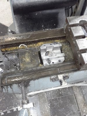
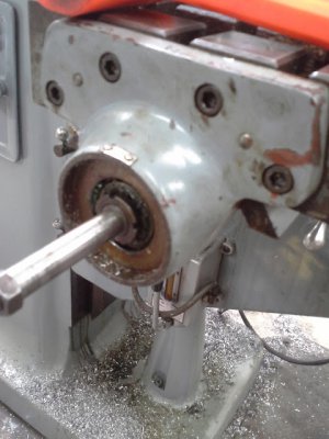
The last part was X axis mount. There are 2 mounts on the table, I re-manufactured the "fixed" mount, and used the stock "simple" mount. Here is a picture of the stock mount. It was cast iron, and used tapered roller bearings with a jam nut and start washer arrangement for pre-load. Not bad, but I wanted better. The stock mount is about 5/8" thick.
Here is my replacement mount. It is 1.5" 6061. It is a very similar design to the Y axis mount, using the same bearings and seals. It is actually 2 pieces; the cylindrical portion screws into the flange, and mates with a shallow taper. Threads are locked with blue lock-tite.
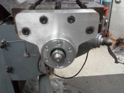
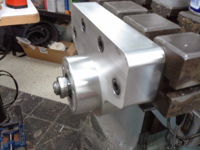
Another shot from the side showing the beefiness of the thing. It is very solid. You can also see the jam nut that fixes the X axis screw.
After initial assembly it took a little tweaking to get things working as I wanted, but after a couple hours of tuning, I made a test pass cutting a circle in aluminum circularity with 0.0015, which I am pretty happy with.


The first part I worked on was the Y axis mount. This started life as a large chunk of 6061 I had sitting around. I roughed out the shape on the mill and finished the bearing bores on the lathe and got a decent (medium) press fit. The bearings were open, so the mount was designed for double lip seals on both sides. The hole assembly was packed with grease and the retainer on the front holds the whole thing together. Here is a view of the whole thing assembled, with the already machined Y axis screw in place.

Here it is installed on the machine. The motor mounts are the same ones I have been using since I started, just 1/2" 6061.

After gaining a little confidence with the Y axis, I purchased a 5 foot section of screw stock and 2 more ballnuts for the Y axis. I also purchased a big chunk of hot rolled steel and some DOM tubing for the yoke. The original yoke on the machine used bronze nuts, and was not going to accept the ballnuts, so I had to fabricate a new one. I did this in 3 sections, 2 large pieces made from the HRS, connected with a piece DOM tubing using my MIG welder.
Here you can see the completed yoke from the top side. As you can see, it is a pretty simple design. The "bulge" in the middle is there to acomidate the pre-load nut. More about that later. I am using square ballnuts, so the channel is square, and the ballnuts just slide right in. A flange attached to the ballnuts screws into the yoke.

Here is a test fit with the ballnuts and the yoke. The large white piece is the preload nut.

The yoke is installed way down in the belly of the beast. It requires that the table be removed and both the X and Y screws. I got very good at removing the table. I think I had it down to about 15 minutes. Each time I needed to take measurements, or test for fit, I had to tear things apart.

Here is a shot with the X axis nut installed as well. You may notice that 2 of the corners are clipped off. Well, as it happens, the yoke has to be installed rotated 90degrees, fed down into the cavity, and then rotated 90degrees to the final position. I didn't really test this until final assembly and it wouldn't go. I had to pull it back out, dog-ear the corners with a hacksaw and files, and try again. Looks almost like I planned it. In this shot you can also see the felt wipers and their retainers. These are just 3/16" soft white felt with holes cut slightly undersized for the screw minor diameter. The felt is soft enough to conform to the screw, and makes a really nice seal. The nuts are packed with the same grease as the ballscrew supports. Rather than purchase pre-loaded ballnuts from the manufacturer for an obscene price, I purchased to non-preloaded nuts and made my own pre-loaded nuts. They worked out really well. The white piece is a chunk of delrin, threaded to match the ballnut. The opposite end has a step to accommodation 12 belleville washers stacked 6/6 (like this >>>>>><<<<<<) for a total preload of about 200lbs. This was tightened against the adjacent nut until it nearly bottomed out.

The last part was X axis mount. There are 2 mounts on the table, I re-manufactured the "fixed" mount, and used the stock "simple" mount. Here is a picture of the stock mount. It was cast iron, and used tapered roller bearings with a jam nut and start washer arrangement for pre-load. Not bad, but I wanted better. The stock mount is about 5/8" thick.

Here is my replacement mount. It is 1.5" 6061. It is a very similar design to the Y axis mount, using the same bearings and seals. It is actually 2 pieces; the cylindrical portion screws into the flange, and mates with a shallow taper. Threads are locked with blue lock-tite.

Another shot from the side showing the beefiness of the thing. It is very solid. You can also see the jam nut that fixes the X axis screw.

After initial assembly it took a little tweaking to get things working as I wanted, but after a couple hours of tuning, I made a test pass cutting a circle in aluminum circularity with 0.0015, which I am pretty happy with.


