With my shaft fit solved it is time to put the gear box together. Here is how you do it. I will leave out details like lubricating each part and basic alignment and step thru just the basics.
This link will help alot with your parts.
http://www.lathe.com/gearbox.htm
First step is the input shaft assembly. One shaft, two gears, one spacer, one key and one clip. Note that the gears are both stepped but one is keyed and the other bushed. The keyed gear is first. The spacer and clip go on the end to secure it all.
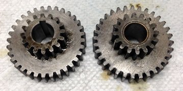
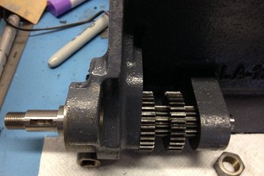
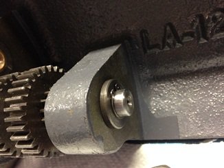
Next is the gear cluster shaft. Two sides to this one. Left side first meaning the side the input shaft is on. The build is from that side.
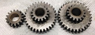
One shaft & three gears. All three gears are bushed and two of them are identical stepped. In fact they are the same as the bushed stepped gear from the input shaft.
Slide the shaft into the housing with the keyed end first. First the small gear and then both stepped gears. Do not leave any shaft sticking out of the last gear.
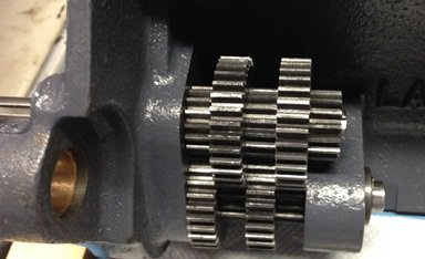
Now the right side. This is the trickiest part of the build. 9 gears, one key and one spacer. Note that all the gears are keyed as well as the spacer.

First step is to orient your key. You should have a witness mark on the key from the set screw in the spacer. That is the side that goes into the slots in all the parts. Test fit your key into each part.
Place your gears out in order from smallest to largest. (reference the link above for more detail) Note that the largest gear has chamfers on the sides of the teeth and that you will have two of one of the gear sizes. Of those two identical gears, one of the them goes on the far end next to the largest gear and the other is in line with the rest of the gears.
Take one gear, place the key into the gear and find a rod that will go into the space that is left and is long enough for the entire gear/spacer stack. an X-acto knife handle works great. Place the key into the spacer and over the handle and start putting each gear in line. Don't worry too much if they do not seat. You are trying to get them in line and basically oriented.
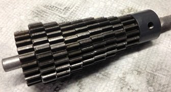
Pull the handle out and now be careful with the stack to maintain alignment. Place the stack it into the housing. Mine was a VERY tight fit axially so i had to tap it carefully in place. Make sure you know where the key is and where the slot is in your shaft. Align them the best you can.
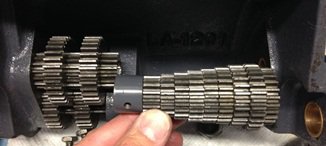
Now start tapping the end of the shaft into the housing. As you hit each gear, finesse it into alignment so the gear engages the key. It is actually pretty easy as once you get the key into the first gear and as long as the gears are sort of still engaged into the key the shaft self aligns. Watch the key to make sure it does not migrate down the shaft. If it does and enters the far bushing then the system will lock up. Tap the key back down the shaft and continue the alignment.
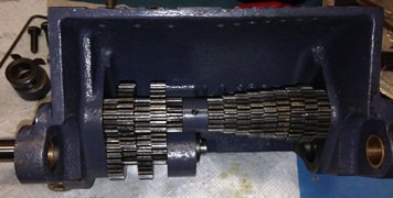
Once complete test that it turns freely. (This is where i figured out i had the sticking shaft. Had to take it all apart)
Note that the left side and right side will not spin together. Once you are happy then lock the set screw in the spacer.
Next is the selector gears. One shaft, two gear assemblies, two small gears, one collar and one pin. Pretty straight forward.
The only thing to note is the orientation of each selector handle. Note that one side is wider than the other where the shaft passes thru. The wide parts go toward the outside. Make sure the handles slide left to right nicely as this is what you will have to move to select your gears. The small gear is placed inside the bore as you pass the shaft thru. You have to align both the bore and the key. Once you are done, secure the end with the collar and drive the splitting pin thru the hole midway along the shaft. (That keeps the left handle on the left side) Again check for smooth operation.
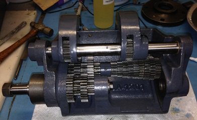
Last step is the lead screw. One screw, one spacer, one key and one nut. See left side of picture below. Make sure the gear only touches the far left gear. You now see why the largest gear has chamfers on it. Easy.
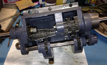
Done. Re-check operation and get ready to install.
You should still have parts. The left side input gear, one spacer, and one nut as well as the left side gear assembly. (Banjo i think it is known as) You also should have the parts to mount the box. Note that if you took out the alignment pins in the box to re-install those at this time.
That is how you put a box back together. You will note that my box is also still missing the ID plate. I will install that later.


