Grizzly G4000 lathe, undressed

Thorn3

Registered
Registered
Joined
Apr 14, 2014
Messages
7
Hello all,

I would like to complain about the manufacturing practices regarding the Grizzly G4000 lathe. But... my mind now resides in too deep a state of shock to do anything but laugh and move on with repairs.

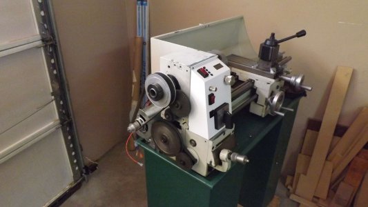
I have had my G4000 lathe for several years. I have had my issues like anyone else using a lathe in this price range. Several (external) mods have been employed to make it safer, easier to use and more accurate. The time came for me to replace the worn out AC motor. In the process of preparing her for a DC motor installation, with custom control panel and electrical housing, I decided that the cheap paint job may as well go while I am at it. After all, who orders machines painted in green hammer paint, then repaints them (without taking the machine part) in cheap, house-paint-like white? I like white... but why not just order them that way?
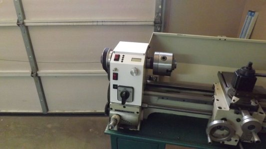
Controller_2.jpgPanel_9.jpgPanel_10.jpg

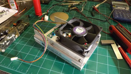
The pictures show the controller with CPU fan, the DC motor installed for testing and the new control panel built and installed. It was at this point I decided to go the new paint route and wound up entering the dark, mysterious world of Asian machines undressed.
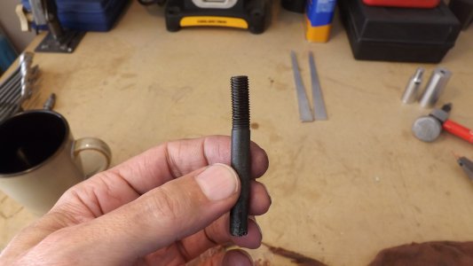
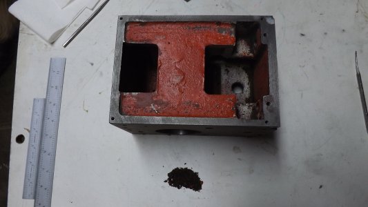
DSCF1062.JPGDSCF1069.JPG

Shown is a bent part from the saddle. Did they not see this was bent before installing it? And... 'how' did it get bent? Next is seen the spindle head, stripped of paint. Casting sand must be breeding in there, as there is plenty of it in every corner. Wiping a finger inside is enough to loosen it. It is no wonder then, why the original bearings sounded like gravel crushers.

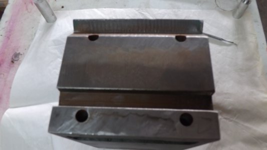
In looking at the bottom of the head, it was seen that this was not properly machined at all. Someone used a hand grinder on it, resulting in a not-so-flat surface that rocks when attempting to stand it up. I do believe this rebuild will result in my seeing things in this machine I have never seen before.
DSCF1068.JPG

I hope you all can see the hand grinding job. No wonder the head didn't want to stay adjusted for very long. Nothing about it is even 'square'. This rebuild is going to take far longer than I had imagined. Complain to Grizzly? LOL.. no, they probably aren't even aware of any of this is going on in that factory in China. I will post more of this rebuild as I go.

Controller_2.jpg Panel_9.jpg Panel_10.jpg DSCF1062.JPG DSCF1069.JPG DSCF1068.JPG
 
Nice panel, the only change I would make personally is adding a big red e-stop switch. I have an HF 9x20 lathe that I bought for parts and to convert to CNC. I was thinking of something very similar for my control panel.

As for digging into something and finding more than you bargain for. Three years ago we remodeled our home. Part of that remodeling was building out the shop in the basement for my CNC equipment (mill and router). While tearing the walls out to put the new 110/220 VAC, we discovered that the wall around where the water comes in from the city was completely rotted through. We had to replace everything within four feet of the spot. Although, I was thrilled to find this bad news. In the seven years we had lived in the house we had problems with moisture along that part of the wall and in the carpeting. We found that hole where the city water came in would allow heavy rains to come through the walls, also the water pressure regulator that was there was leaking. All of this was completely sealed away out of sight, no one knew it was there. I was happy to find it and fix it though. Oh - and now I have a shop sink since someone in the past had ran hot/cold water and drainage to the same spot.

-Freeman
 
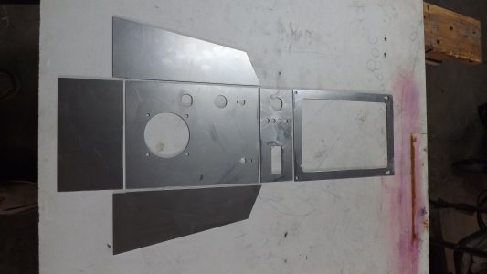
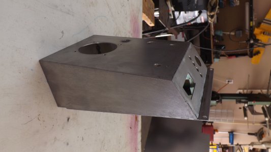
Analias: Thanks. The panel is made from 18 gauge cold rolled steel. Each panel prepared ahead of time, then tack welded together, cleaned up and painted. I originally intended to use a relay and an E-switch. A relay because none of the affordable E-switches could make/break 17 amps. I opted for the three position switch as I am used to it. Only now, I don't have to reach over the spinning chuck to actuate it. It is wired to switch AC to the entire system as well as change motor polarity for forward/reverse, with center off.

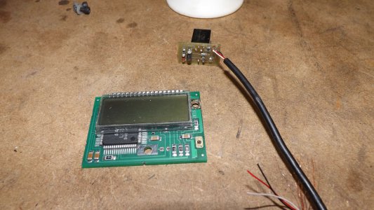
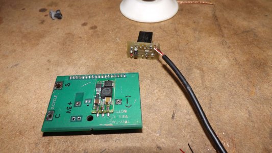
The small screen is actually the PCB from a 'tiny tach' used for IC engines. It was removed from the potting material in the housing. The PCB is mounted internally to the console via one stand-off. A 300mA switch mode regulator powers it and the sensor. This circuit requires only one input pulse per revolution.

The LED's show status of the controller board. Remove the LED's from the controller and replace with wires. Lead wires to LED's on the control panel and there you go. No need to take the power box apart to see the status of the controller board. I used three green and one red LED. If the red one comes on... then the controller is in an over-current condition. Otherwise the three green ones simply indicate those functions are on and working.

The larger pot knob under the tach is the speed control pot. Pretty simple. The smaller pot knob is for a future application. I plan to install a small fluid system. The switch to turn it on and the pot to adjust flow rate. Or, it could be used for a power feed... anything really.

The switch to the left of the LED's is actually just there to turn the work light on and off... or whatever else is plugged into the plug that switch controls.

It was important for me to design the control panel with simplicity in mind and an open area in which to move my hands without hitting other things. This is why the main switch and speed control pot are relatively isolated.


Tach_1.jpgTach_2.jpgDSCF1043.JPGDSCF1046.JPGDSCF1049.JPGDSCF1051.JPG


Ouch... two didn't come through rotated. Ah well... The two top screws for the panel are the ones used to hold the original panel to the spindle head. The two lower ones were solved using key holes. Insert panel high, slip down onto lower screws.. put in upper screws. Pretty easy and keeps it clean. I used basic hand tools to make the panels, so anyone can do it. I had to make the circuit for the sensor. The switch mode regulator is a prototype a friend and I put together.

I hear you on hidden house issues. Flooded one of my bathrooms by opening the outside hose valve. Whoever installed it didn't do so from inside the wall, they just screwed it in from outside the house. Hmm... LOL!

Tach_1.jpg Tach_2.jpg DSCF1043.JPG DSCF1046.JPG DSCF1049.JPG DSCF1051.JPG
 
In looking at the bottom of the head, it was seen that this was not properly machined at all. Someone used a hand grinder on it, resulting in a not-so-flat surface that rocks when attempting to stand it up.
I see a surface grinder in your future... always satisfying to have the right tools for the right job.

That being said, however, aren't the critical surfaces there where the headstock sits on the rails of the bed, rather than the broad flat surface? Or were you commenting that the headstock surface that engages the flat rail of the ways isn't actually flat?

Killer job on the control box.
 
tmarks11: The head sits directly on the flats of the bed, but does not touch the V rail. There is a sizable gap between them, to allow the head to move in reference to the bed to allow alignment.

The head was resurfaced allowing the head to sit flat. Once the rest of the assembly is finished, the head will be pivoted right or left to align, as well as shimming under the front or back.

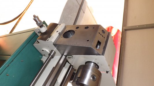
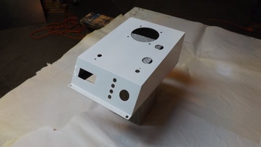
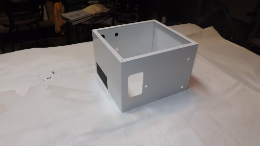
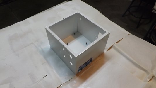
The electrical box for the wall side of the head is almost done. Once painted, it will be mounted on the head and all wiring done. Hopefully this will occur this weekend.

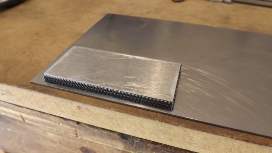
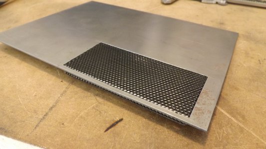
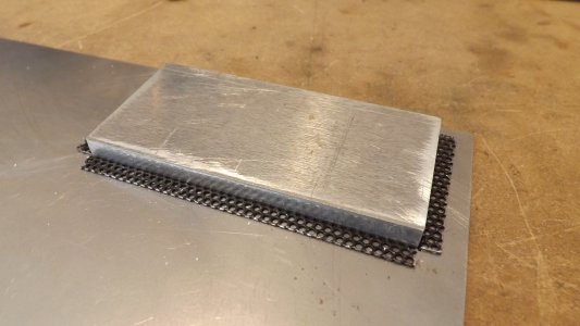
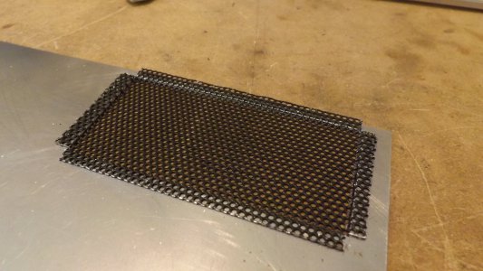
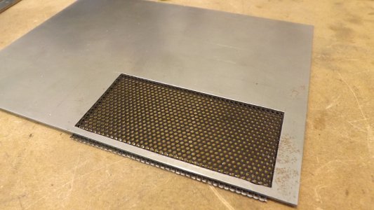
I wanted the exhaust and intake ports for the fan to be screened to protect from large debris. On the intake side, which will be in the front panel, a filter will be used along with the screen so as not to ingest debris onto the PCB. The filter will be located in a housing just inside the front cover, with a short duct leading from it, directly to the fan shroud.

As can be seen, the screen mesh is first shaped over a plug, milled to fit the hole, minus the thickness of the screen mesh. The screen mesh is bent over the plug. The plug is inserted into the hole and the tabs bent over. The screen mesh will be glued to the interior wall. It would have been more simple to cover the hole with a piece of flat mesh, but forming the mesh to be flush with the exterior of the wall adds a design feature that is more my style. DSCF1177.JPGDSCF1178.JPGDSCF1179.JPGDSCF1180.JPGDSCF1181.JPGDSCF1182.JPGDSCF1185.JPG
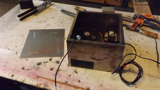
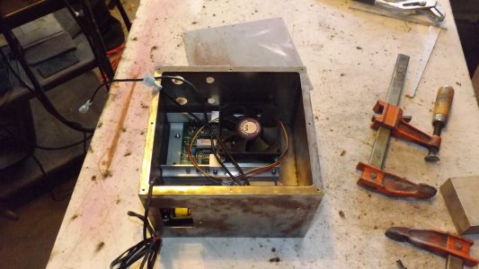
Looks like my cursor was in the wrong place when inserting the pictures. What is seen inside the box, is the motor controller with fan, a 12 VDC 2A switch mode regulator and the motor choke. Some people use the choke, some do not. I personally believe that this type of controller should use the choke due to changing load during machining. The switch mode regulator is used because it is smaller than a linear type and has higher output for its size. It will be used to power the LED worklight that I will make for the lathe, as well as the tachometer circuit/sensor and the accessory circuit.

DSCF1177.JPG DSCF1178.JPG DSCF1179.JPG DSCF1180.JPG DSCF1181.JPG DSCF1182.JPG DSCF1185.JPG
 
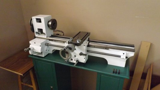
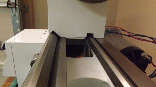
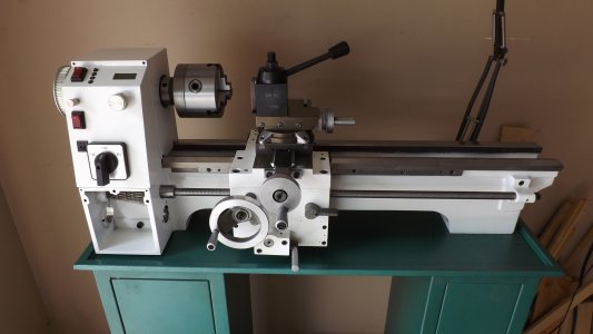
It took a while, but the rest of the lathe is pretty much done and waiting for the control panel and electric box. The entire assembly had to be taken apart and stripped of the original paint. The head was fully cleaned out to remove the remaining casting sand and fine bits of shocked metal. A good deal of grinding was done to correct the more outstanding casting flash. Parts were machined to make them more accurate. The bed surfaces, fillets were filled (automotive body putty) to correct for surface errors in the castings, sanded, then painted with an epoxy paint intended for appliances. All in all... it is like a brand new machine that is better than new. The second picture shows the gap between slots and rails on the head.

DSCF1186.JPGDSCF1187.JPG

- - - Updated - - -

DSCF1140.JPG This shows the control panel during a test fit. I plan on printing some stick-on sheets to better call out the various functions on the panel.

DSCF1186.JPG DSCF1187.JPG DSCF1140.JPG
 
Painted the electrical box today. Had to remove the light rust due to high humidity lately. No problem, came out pretty good. The exhaust screen is sitting in place to show how it will look when done. Will glue it in prior to installing the motor controller, using a rubber based adhesive.

Next is to finish off the cover panel that will house the intake filter and duct. Then of course install all components and wire it up.

DSCF1189.JPG DSCF1192.JPG
 
Back
Top