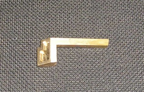
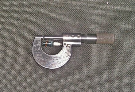
32x40 H -- Gas Engine

OK so its back to work
Looking around I found I had to many half finished job so I got into clearing up some of them.
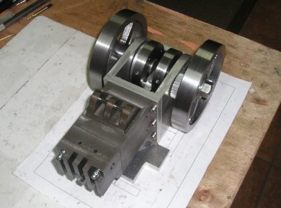
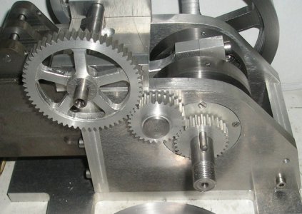
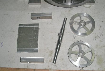
The intermediate timing gear did not have a shaft so one was made and the gear planted.
the side plates had to be milled out to take the bearing retainer plates that I had not made yet??
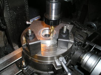
P1013008.JPG
So that had to be done.

Also the piston was not finished the blank had been made early on and lapped to the cylinder
but I kept making excuses to my self that I had not ordered the rings. so it was put to one side ( I still haven't ordered them ) "Do other's do this" ,
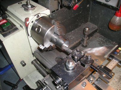
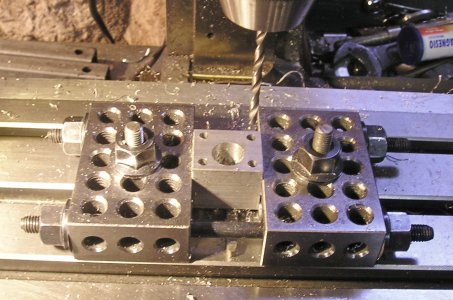
So find the blank and drill the wrist pin hole.
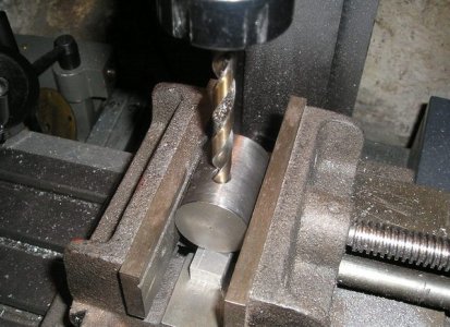
P1013011.JPG

Turn the inside of the skirt.

P1013010.JPG

Then mill out the recess for the small end,
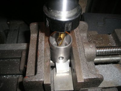
P1013013 (2).JPG

Now fit it all together to see how it fits,
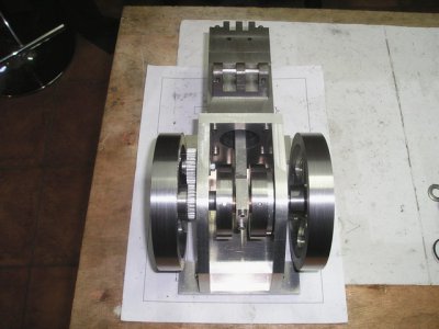
P1013014 (2).JPG

P1013015 (2).JPG

That looks Better.


Brian.
P1013008.JPG P1013011.JPG P1013010.JPG P1013013 (2).JPG P1013014 (2).JPG P1013015 (2).JPG
 
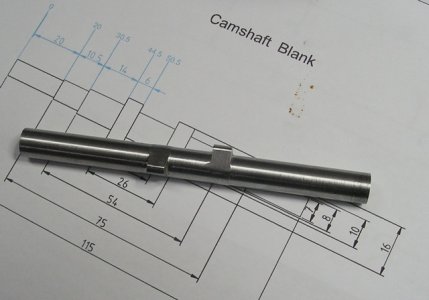
Next step is the blank for the cam shaft.
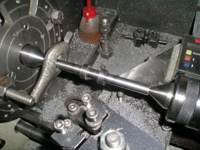
Turned between centres so I can return it to the lathe after the cams are cut and reduce the shaft to fit the bearings
and the timing gear etc.

P1013019.JPG

Next step will be on to the mill,with the rotary table, but its to cold at the moment for my brain to get up to working temperature for this job.

Brian.

P1013019.JPG
 
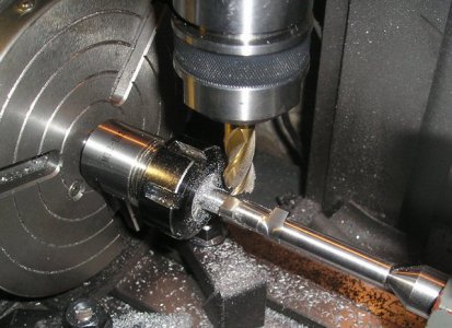
Hi ho Hi ho on to the mill we go, remove the 240° to form the base circle and we have a camshaft.

P1013020.JPG

P1013022.JPG


Slowly slowly Brian.

P1013020.JPG P1013022.JPG
 
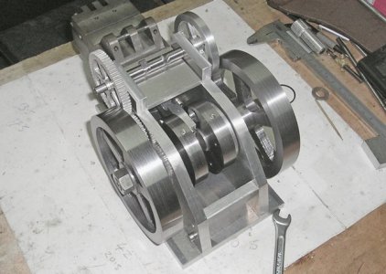
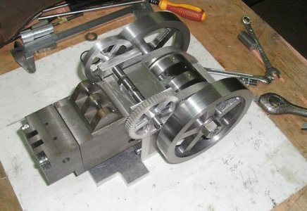
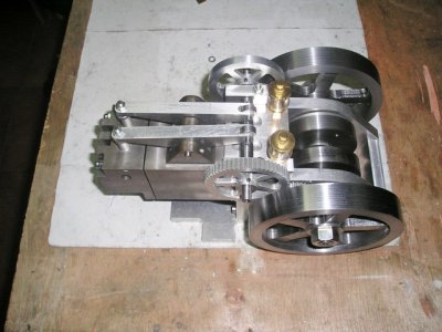
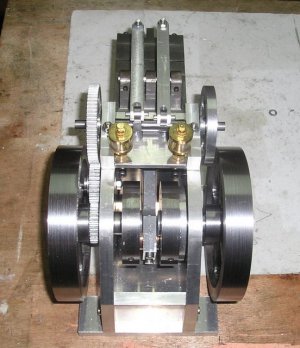
A few more photo's showing the cam sub assy in the rough. two drip oilers will be mounted between the can shaft supports on the flat plate to lube the cyl and big end.

P1013026.JPG

P1013025.JPG

P1013024.JPG

Keeping going Brian.

P1013026.JPG P1013025.JPG P1013024.JPG
 
The next problem was fixing the sub assy to the crank case with the correct gear alignment. a bit of a fiddle with a transfer punch and it was done.


P1013030.JPG


The oilers arrived in the post so that gave me the next job drill and tap 1/4 x 40 and in they go pipework to follow.

P1013036.JPG

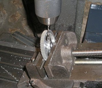
Almost forgot the cam gear and the ignition timing wheel had to be drilled to take the grub screws for location during timing operations, final fixing will be by a end cap and screw.

P1013031.JPG

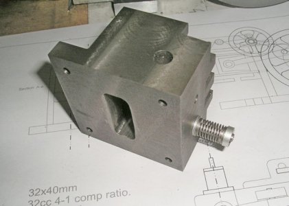
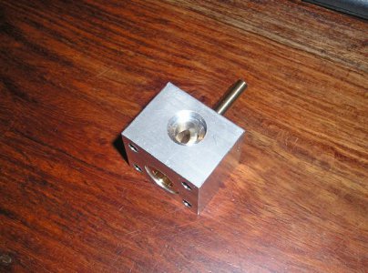
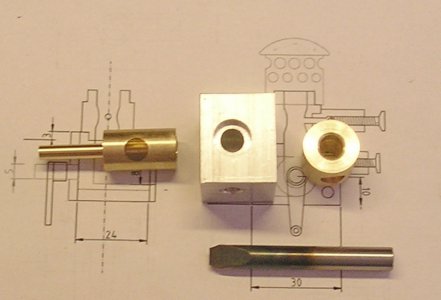
I have made a start on the carburettor It's taken a long time on the CAD to get this so it looks as if it's going to work.

So I have started cutting metal by making the throttle body.


Brian

P1013030.JPG P1013036.JPG P1013031.JPG P1013035.JPG
 
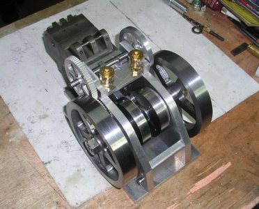
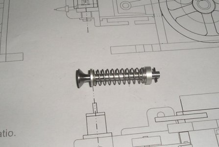
Today has been a big day the valve retainers and pins made and the valves fitted.

P1013042.JPG

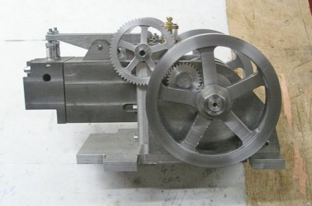
The rockers made and fitted .

P1013044.JPG


P1013048.JPG

P1013051.JPG

The rockers are going to be T beam in section and tapered toward the valve end so I have a little tidying to do but today it looks like an engine for the first time.
waiting for the plug and gasket material, then I can see what the compression is like.
Still a lot to do.

Brian

P1013042.JPG P1013043.JPG P1013044.JPG P1013048.JPG P1013051.JPG
 
Limited time in the shop today just to cold.

made progress on the carburettor.

P1013052.JPG

Brian.

P1013052.JPG
 
Short time in a very cold shop today.
Managed to drill the jet holes for idle and main ,and make the venturi , this involved making a form tool to cut the internal shape. Hope for a better day tomorrow..

P1013055.JPG

Brian.

P1013055.JPG
 
Made the mixture controls today and started on the outer end plate.
Did a quick fit up to see how it all goes.

P1013059.JPG

Coming along.---Brian.

P1013059.JPG
 
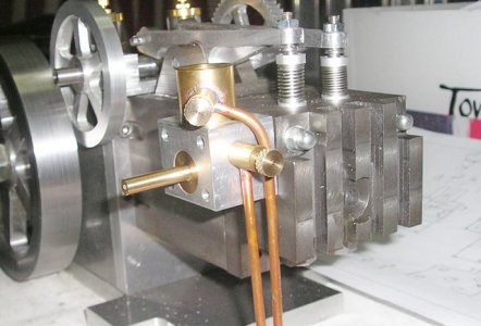
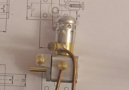
The carb is getting nearer to a working item just the throttle leaver to do, still awaiting the diaphragm and valve for the gas demand valve.

P1013061 (2).JPG

Started on the feed system that takes oil from the drip feed into the big end. lots of head scratching to get this right.

P1013064.JPG

The spark plug arrived today, How's this for a little darling.

P1013058 (2).JPG


Its moving on..Brian.

P1013061 (2).JPG P1013064.JPG P1013058 (2).JPG
 
Back
Top