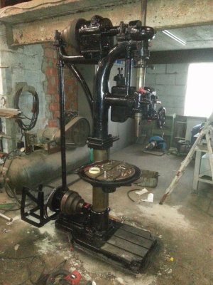
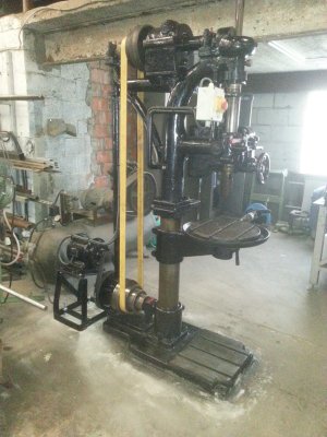
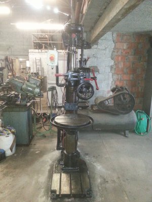
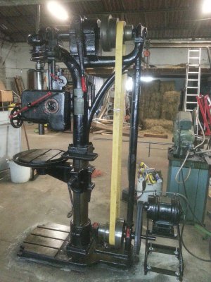
Wimow BS32 German Drill-press

orjo

Active User
Registered
Joined
Jan 29, 2014
Messages
64
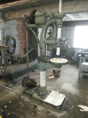
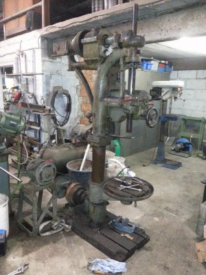
Saterday 10th january I picked up my newly acquired drill-press and brought it home.
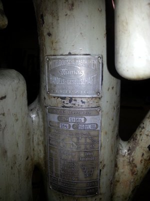
It is fabricated in Germany Leipzig on 10 november 1920.
2015-01-12 13.47.51.jpg
The specifications are:
MK 4 cone, 8 speeds from 313 to 9 rpm.
It has auto feed of 0.14/0.26/0.45 mm/rpm.
2015-01-10 15.57.25.jpg
Totday I got it cleaned and gave it a good inspection.
I noticed some faults. No big ones but they do need attention.
2015-01-12 13.44.54.jpg

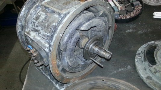
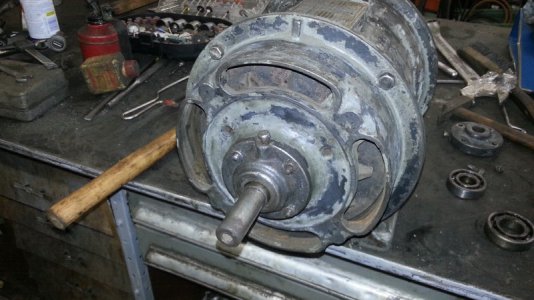
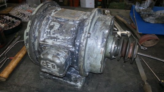
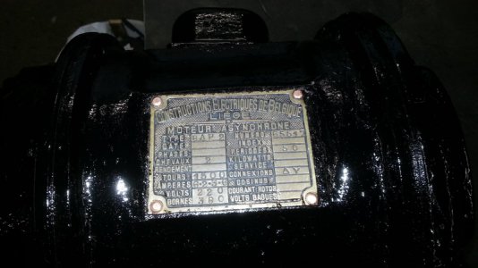
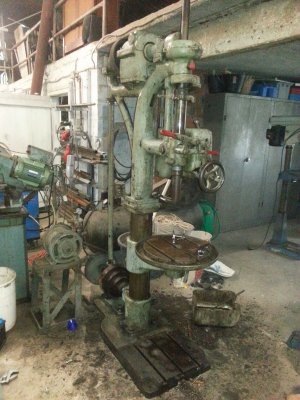
The motor is a 2 hp 1400 rpm 3 fase 220/380 volts motor set at 380 volts. It sits on a cradle wich seems to be attaged at a later date. The motor is not a German motor but a Belgium motor.
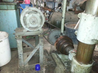
2015-01-12 13.48.38.jpg
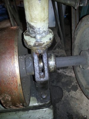
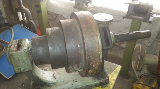
The driven axle is at the bottom oof the machine and is supparted by two bearings. On top of these bearings is a small triough which the axle is greased. The top axle also hase to simular bearings. There is only one door at hand. The other three will have to be made.
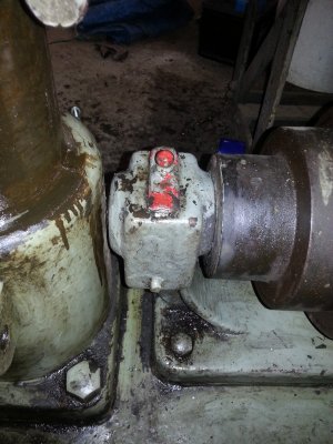
2015-01-12 13.45.05.jpg2015-01-12 13.45.09.jpg2015-01-12 13.49.54.jpg

After the first cleaning a dissasambled the engine cradle. It is going to be discarded.
I will make a new cradle and mount the engine on top of the axle. So it will take not more place then needed.
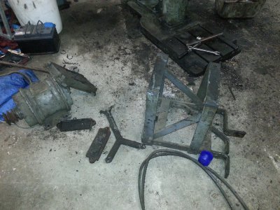
2015-01-12 14.40.33.jpg

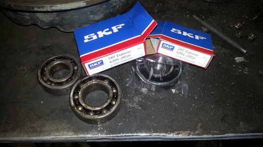
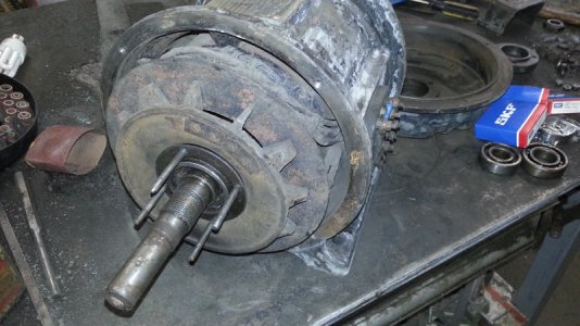
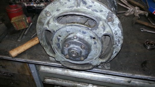
Next I disasambled the engine. When spinning it arround there was a grinding noise, the bearings are gone (lack of oil in the last years of use). The bearings are a 6205 and a 6204 I will get them tomorrow so I can put the engine back together.
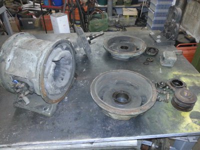
2015-01-12 16.48.30.jpg

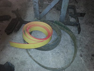
The flat belt that was on it was cut when I disassembled the drill for transport. I already have a new one.
2015-01-12 14.47.19.jpg

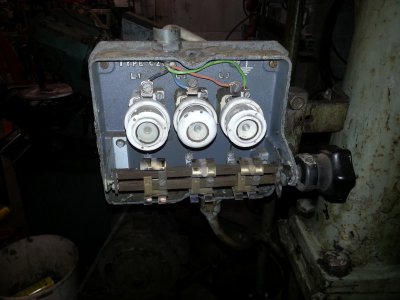
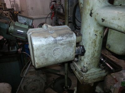
The electrical switch is an old one and will be discarded. I will mount a new one with some more safety features so i can operate it in a safe manner.
2015-01-12 13.56.17.jpg2015-01-12 13.59.05.jpg2015-01-12 14.05.30.jpg
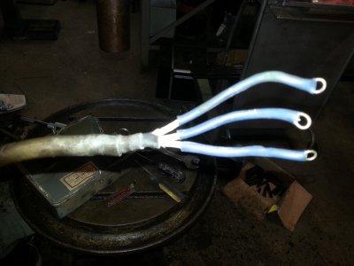
The cables that went from the switch to the engine is an old cable it has insulation with some kind of fiber, rubber and led, it will be replaced.

I will post an update as soon as possible.
Bye for now.

2015-01-10 15.57.25.jpg 2015-01-12 13.44.54.jpg 2015-01-12 13.48.38.jpg 2015-01-12 13.45.05.jpg 2015-01-12 13.45.09.jpg 2015-01-12 13.49.54.jpg 2015-01-12 14.40.33.jpg 2015-01-12 14.47.19.jpg 2015-01-12 13.47.51.jpg 2015-01-12 16.48.30.jpg 2015-01-12 13.56.17.jpg 2015-01-12 13.59.05.jpg 2015-01-12 14.05.30.jpg
 
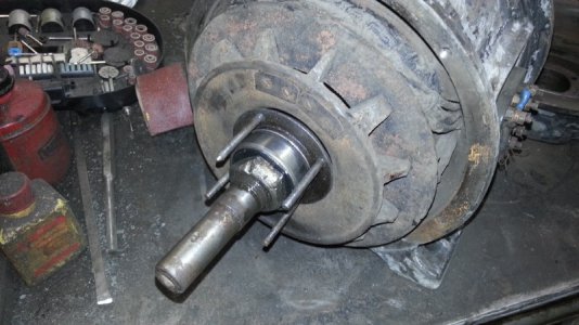
Today I got the motor back together.
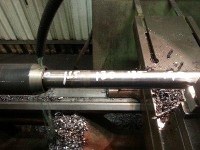
I installed new bearings from SKF 6204 /6205 2RS.
They are blinded with a built in rubber seal at both ends so they do not need to be lubricated again.

Here are some pictures 2015-01-14 15.36.09.jpg2015-01-14 15.36.19.jpg2015-01-14 15.36.27.jpg2015-01-14 15.40.10.jpg2015-01-14 16.22.33.jpg2015-01-14 16.27.14.jpg2015-01-14 16.39.35.jpg2015-01-14 16.51.27.jpg2015-01-14 16.51.45.jpg

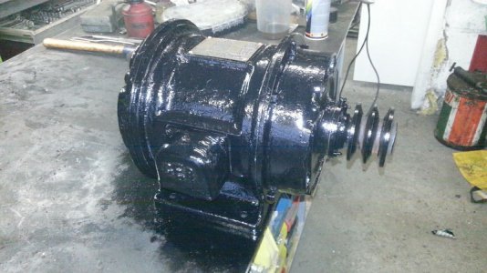
I cleaned everything degreased it and gave it some coat of glossy black. I think blach was the orriginal color for this engine.

The grinding noise is completly gone, no noise at all.

2015-01-14 15.36.09.jpg 2015-01-14 15.36.19.jpg 2015-01-14 15.36.27.jpg 2015-01-14 15.40.10.jpg 2015-01-14 16.22.33.jpg 2015-01-14 16.27.14.jpg 2015-01-14 16.39.35.jpg 2015-01-14 16.51.27.jpg 2015-01-14 16.51.45.jpg
 
now that's what I call a drill press! keep up with the pictures, it's fascinating!
 
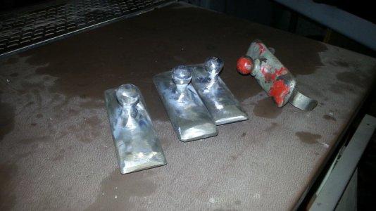
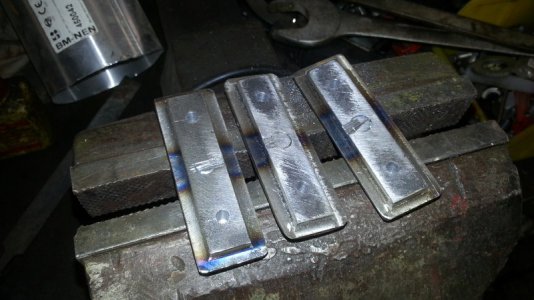
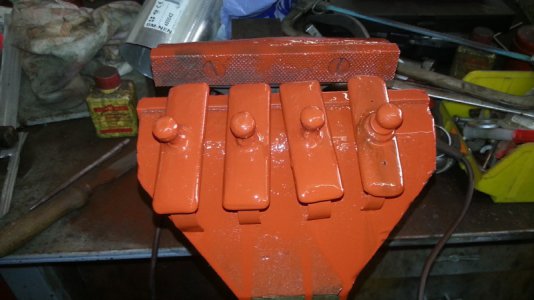
Today I made the missing grease doors.

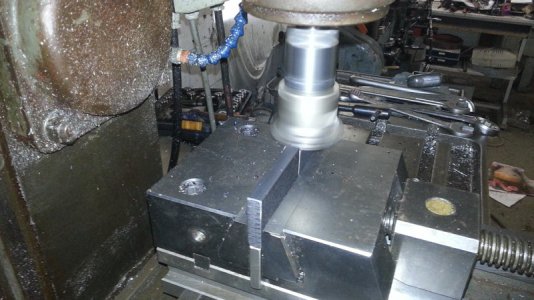
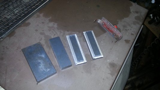
I took a piece of flat steel of 10 x 40 mm and dressed it down to 25 mm with the mill.
2015-01-18 10.20.37.jpg

Then i milled the step around the plates.
2015-01-18 11.03.09.jpg

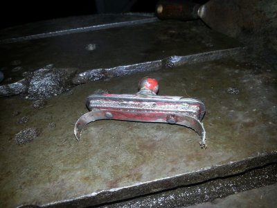
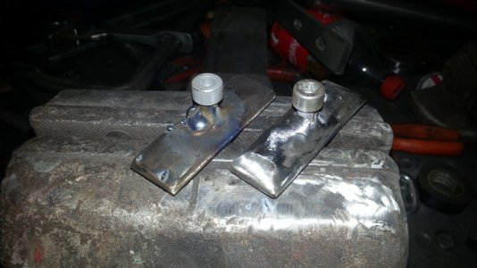
Next I drilled a hole of 8 mm in the center of the caps and welded in a allen bolt of M8 x 40.
Then cut of the remaining piece piercing throug the cap and grinded the lot in chape so it matches the original cap.
2015-01-18 11.29.45.jpg2015-01-18 11.38.33.jpg2015-01-18 11.51.02.jpg

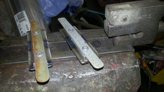
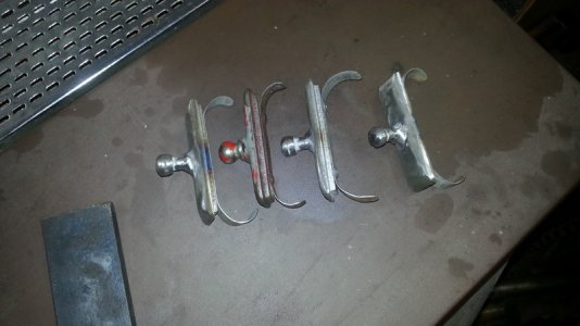
Next i took a piece of steel band (the one that they put arround shipping crates) I cut them to size. Puched 2 holes of 5 mm, drilled 2 holes of 4.5 mm in the caps and connected the 2 with some blind rivets and put some paint on them.
2015-01-18 11.56.28.jpg2015-01-18 11.58.12.jpg2015-01-18 12.08.00.jpg
Al that is left is to give them a coate of red paint and they can be mounted in place.

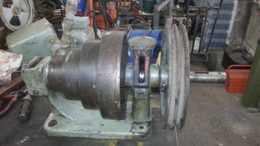
I still had some time left and decide to take care of the driven axle of the drill at the bottom of the drill.
I compleetly took it apart. The bearing faces look a bit scored but are still in rather got condition. I cleaned out the grease pockets and cleaned al the other parts.
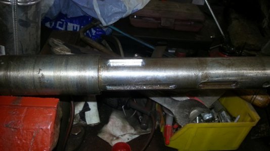
The axle was mounted on the lathe and a new keyway of 10 mm wide was milled at an angle of 45° to the other one already in place.
I did that because I want to mount the v-pulley from the end of the axle near the bearing block. That way I can mount the motor as close to the drill as possible.
2015-01-18 13.10.34.jpg2015-01-18 14.14.14.jpg2015-01-18 14.40.55.jpg

Next I will change the engine cradle.

2015-01-18 10.20.37.jpg 2015-01-18 11.03.09.jpg 2015-01-18 11.29.45.jpg 2015-01-18 11.38.33.jpg 2015-01-18 11.51.02.jpg 2015-01-18 11.56.28.jpg 2015-01-18 11.58.12.jpg 2015-01-18 12.08.00.jpg 2015-01-18 13.10.34.jpg 2015-01-18 14.14.14.jpg 2015-01-18 14.40.55.jpg
 
This machine is progressing nicely,The doors look like a good match! Thanks for taking the time to document this refurbish !
 
Orjo,

Congratulations on getting such a fine old machine tool, As well as being very useful it is a lovely machine with a charm not obtained in todays drilling machines, you have a machine with lovely flowing shapes unlike todays machines which are not always appealing to the eye
You are doing a lovely rebuilding exercise especially your doors and the little electric motor, Like you I think the motor should be black
Are you sure the bearings are grease lubricated in the bearings on the bottom drive axle ? It looks to me like an oil pocket which should be filled with oil, the shaft having in the pocket a little loose running ring about 4mm wide which picks up the oil from the bottom of the pockets and keeps the shaft oiled when it is working, You will see on the outside of one of the pockets near the bottom a screwed plug for draining off dirty oil , I have come across that system before on a German and British machine tools

Please keep us supplied with photographs and information on your excellent rebuilding work Well Done !

Core Oil
 
Orjo,

Are you sure the bearings are grease lubricated in the bearings on the bottom drive axle ? It looks to me like an oil pocket which should be filled with oil, the shaft having in the pocket a little loose running ring about 4mm wide which picks up the oil from the bottom of the pockets and keeps the shaft oiled when it is working, You will see on the outside of one of the pockets near the bottom a screwed plug for draining off dirty oil , I have come across that system before on a German and British machine tools

Core Oil

I think your right, there are rings in there, I thought of it because grease can not flow in to the bearings.
Any idee which kind of oil to use? a light grade or a heavy grade?
 
Here is a new update on the progress. It runs.

In chronological order I will discribe what I have done.

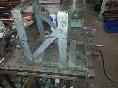
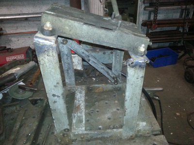
First I took the engine cradle and changed it so i could mount it on the floor behind the machine.
The base of the cradle was rivetted with big steel rivets, the way they used to do long time ago.
A few parts where cut-off and the base for mounting the engine was tilted. I did this to be able to give more tension to the belt faster and to keep the distance to the other puley at a minimum.
2015-01-28 12.26.16.jpg2015-01-28 15.21.12.jpg

These parts were painted Black.

The engine mounting base was cleaned an painted.
2013-12-02 11.25.09.jpg

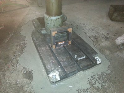
Next I set the drill at its final mounting place and drilled the holes to mount it to the floor.
With a machinst level I mad sure that the base was level with the floor. With some fast drying cement I filled the gaps so everythig sits nice and tied.
2015-01-28 14.14.43.jpg

The next day when the cemant was dry i torqued the bolts down and started degreasing the machine. The items that may not be sprayed where taped of and the put a few coats of black pint on with a few spray cans.

Then the engine was postioned after the machine and bolted to the floor.
The engine was mounted on the the cradle and the new belts where put on and tensioned.
Then The rotating parts of the machine where lubricated so i could sart her up but first i had to make the electrical connections.

As soon as the connetions where made i tested the engine and it was running in the right direction from the first moment.
It is a 380 vlot 3 fase engine.
2015-01-29 14.20.57.jpg2015-01-30 15.41.35.jpg

Then the flat belt.
First I laid the belt over the puleys and took a measurement. Cut the belt and tied the belt together with metal pieces.
The belt was laid on and the engine was started.
That did not went good. Assoon as the engine was started teh belt run off the puleys.
So I needed more tension.
I then recalled that I had a little book with a calculation for the flat belt. Calculated measured and refitted and voila it is now running perfect.

2015-02-06 11.17.02.jpg2015-02-06 11.17.12.jpg2015-02-06 11.17.28.jpg

No I have a question.

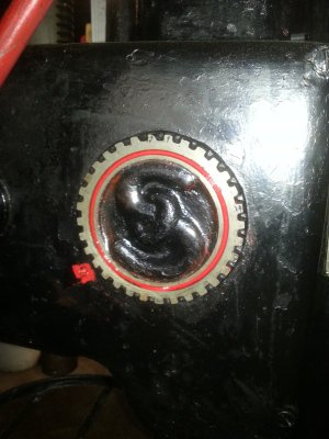
On the side cover for the automatic feed is a logo.
Does anybody know what it stands for Brand?
2015-02-06 11.18.12.jpg

2015-01-28 12.26.16.jpg 2015-01-28 15.21.12.jpg 2013-12-02 11.25.09.jpg 2015-01-28 14.14.43.jpg 2015-01-29 14.20.57.jpg 2015-01-30 15.41.35.jpg 2015-02-06 11.17.02.jpg 2015-02-06 11.17.12.jpg 2015-02-06 11.17.28.jpg 2015-02-06 11.18.12.jpg
 
Back
Top