120v To 240v Help Needed

calstar

Active User
H-M Supporter Gold Member
Joined
Sep 26, 2013
Messages
408
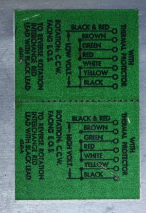
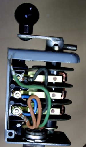
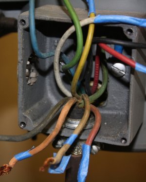
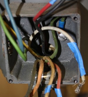
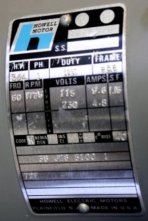
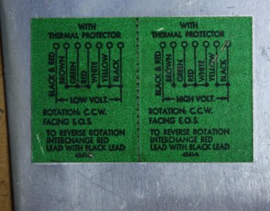
See the attached pics for reference. The colors of the wires do not match the colors shown on the wiring diagram, hoping someone can help me out. I assume the forward/reverse switch also must be changed so please take a look at that as well.

thanks a lot, Brian
IMG_7290_zps7i5zog9u.jpg

"With thermal protection", didn't have it previously
IMG_7286_zpsgfocgszl.jpg

IMG_7286_zpsv5f2wnw5.jpg

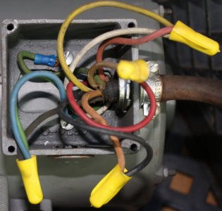
as wired for 120v, wire colors do not match diagram so....?
IMG_7282_zpsd09kvjl3.jpg

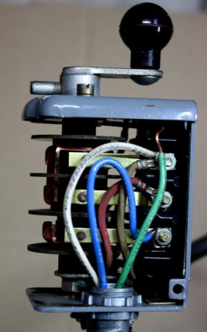
switch in off position, pulling knob toward you in first pic below runs forward, loose ground wires attach with switch box mounting screws
IMG_7292_zpsqb3jjta9.jpg

IMG_7293_zpswbbl8hbv.jpg
 
Last edited:
if you disconnect the power cord from the motor and snap another picture, it will be easier for me to see the motor taps and therefore easier to help out.
 
if you disconnect the power cord from the motor and snap another picture, it will be easier for me to see the motor taps and therefore easier to help out.

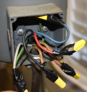
OK, here ya go, thanks. Green, yellow, blue, white, black and red from motor. Brian

IMG_7308_zpsyezksytd.jpg

IMG_730520-20Version202_zps93re13vw.jpg
 
Hi Brian,
the blue wire is capped off.
the motor green and white wires are paired up and paired with the black switch wire.
the motor yellow, is paired up the red switch wire
motor red will go back to white switch wire
motor black will go back to switch brown.

whoever wired it up the first time reversed the black/red pairing and the white/yellow/black pairings respectively which would have the motor turning the opposing direction.
 
Thanks so much Ulma Doctor. So I don't need to do anything in the switch box, its good to go as is?

Brian
 
Hey Brian,
if it ran before on 115v- you'll be good to go on 230v.
the 230v has the windings in series, in 115v the windings are wired parallel

i would ask if there are any transformers in the machine????
you'll need to re-tap them if you do!!!
 
[QUOTE="Ulma Doctor, post: 279479, member: 22605"
...i would ask if there are any transformers in the machine????
you'll need to re-tap them if you do!!![/QUOTE]

Just the stock motor and switch, nothing else on the mill, so no transformers. Brian
 
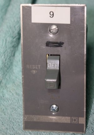
The mill did come with a thermal overload protection switch(see pics) but not installed. The motor does not have a "built in" overload protection reset button so since I have it I may as well install it but need guidance(again), how would I connect it? I'll be replacing the armored cable that hard wired the mill previously with a power cord, makes more sense, I have the mill on a mobile base. Seems like the overload switch would go between the drum switch and the plug on the power cord, but how do I wire the 240, one of the legs to the switch(in and out)?
I'd run the cord from the drum switch to a box for the overload switch and then continue the cord with a plugged end, at least thats my thinking.

thanks, Brian

motor rewired for 240(may be overkill but I'm in the habit of wrapping the connectors)
IMG_731120-20Version202_zpsb4lyytd3.jpg

IMG_7315_zps2z4ykg2r.jpg

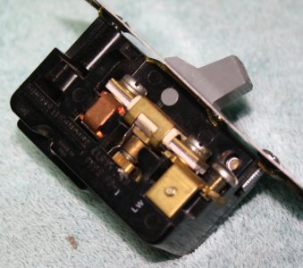
one of the legs connected to these terminals?
IMG_7313_zpsl0qb6rnn.jpg

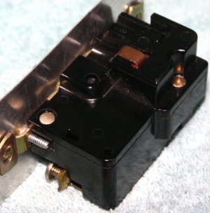
nothing on this side to connect
IMG_7314_zpsru1husqc.jpg
 
there should be 2 terminal lugs on the overload device. you may see another lug if you take off the faceplate.
one power leg power will run through the device, it's contact can be broken by thermal deformation of a bimetallic heater located in the center of picture 1.
you could use the switch red or switch black on the overload device as either leg is 115v in reference to neutral, either wire would give the desired effect.
 
Back
Top