Mbfrontier's Logan 200 Rehab

Today I assembled the tail stock and put it on the lathe. I aligned the stamped indicator marks on the base and housing and called it good for now. I'll fine tune it with a test bar when I get the lathe running.
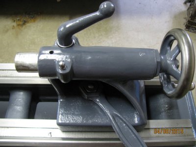
IMG_1019_zpstkf8udor.jpg


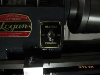
Next, I installed the name plate and temporarily installed the switch plate with only two screws to see what they look like.

First, I'll say I have zero experience restoring name plates. On the name plate, I cleaned the plate with lacquer thinner, used Testor's model paint, and painted the red and black bars. Then, I wet sanded the paint until the raised letters and marks appeared. I then tried to spray clear over the top which turned out to be a mistake. The clear lifted the colors below. I left it to dry completely while I worked on other parts. I wet sanded the wrinkles, rubbed with some polishing compound, and applied some car wax. I could have completely stripped it with lacquer thinner and started over but that aint gonna happen. I'm calling it good.

I cleaned the switch plate the with lacquer thinner and this time sprayed it with Rustoleum black. I sprayed enough to cover the plate but not too much so it wouldn't build up and/or run. I let it dry a couple days and baked it at 12o degrees for 20 minutes. I lightly wet sanded until the raised letters and borders were clean, used polishing compound to finish it before using a little car wax. No clear this time. I think it came out much better and wish I would have done the name plate the same way. Lesson learned. The little bit of exposed brass around the switch hole is covered by the switch retaining ring. I hope this helps anyone else who tries to do this. Forget the model paint and clear and use the rattle cans.
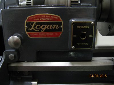
IMG_1023_zpsbw26mxmn.jpg


I think it's safe to say I'm done with name and switch plates and will start on the reverse shifter and motor and countershaft box next.

That's it for now.
 
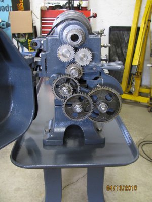
I disassembled, cleaned, blasted, and painted the reverse gear assembly and change gear assembly. I cleaned the gears and sprayed them with Maxima Chain Wax Lubricant which is used to lubricate motorcycle chains. I read about using it on gears somewhere on this website and thought I would give it a try. I also sprayed it on the bull gear, cone pulley gear, and back gears. I've used it before on my motorcycle chains and found the wax keeps it from slinging off of the chain so I'll find out how it works on the gears when I get the lathe running. Here's a picture of the completed gear box.
IMG_1027_zps2jmz60dv.jpg

Next, on to the countershaft and motor box.

That's it for now.
 
Where's the drama. We need drama here. You're just FLYING through this rebuild. Guess that's how it is when you solve all your problems FIRST. :)
 
Hey, Redlineman.
I don't think I had nearly the amount of broken or missing parts that you had to deal with on your rebuild. I'll be happy without any drama the rest of the way. The interesting part for me will come when I plug it in and begin to run it.
 
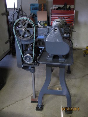
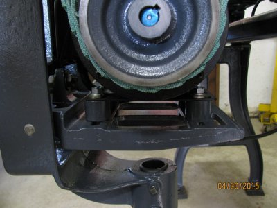
I have been working on the drive box assembly and was finally able to start assembling yesterday. I started by assembling the drive box frame to the motor box frame. Then I installed the peg leg to the motor box frame and attached the drive box to the lathe by inserting the two pins through the drive box mounting holes into the grommets in the headstock mounting brackets. I placed a 1 inch rubber pad and a block of wood on top on the floor for the peg leg to set on. I had to add the block of wood to account for the lathe height increase of the adjustable carriage bolts I'm using to level the lathe. I'll make a suitable base once I get the lathe back up and running.
IMG_1049_zpsnypzmobl.jpg
IMG_1041_zps7evwykvo.jpg

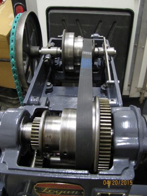
I tightened the countershaft bracket adjustment screws by hand to square the countershaft pulley to the side of the drive box frame and take out any play between the bearing caps and the adjustment screws. I held the screws with a wrench while tightening the jam nuts to make sure the screws stayed put and didn't turn to apply more pressure to the bearing caps. I checked to make sure the countershaft spun free with no additional drag from the bearing caps by spinning the countershaft by hand. I had to position the serpentine belt to try to avoid drag and the linked belt was not installed at the time.
IMG_1045_zpsdgjcx8lw.jpg

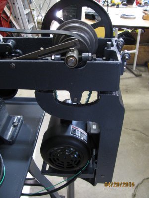
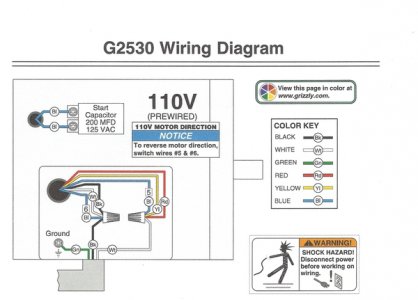
I installed a new 3/4 HP Grizzly TEFC Motor wired for 110 volts. I investigated many motors and liked the reviews and price on this motor that I found online. I sorted out the wiring for the motor and drum switch on the bench and drew up a wiring diagram for documentation so I would be able to get the wiring right when installing and wiring the parts on the lathe. I positioned the motor on the motor bracket and made four one inch spacers to raise the motor so the wiring box on the back of the motor would clear the motor bracket adjustment screw and casting. I was able to compensate by removing two links from the drive belt to account for the increase in motor height. I adjusted the motor position to align the pulley as best I could with the countershaft by moving the motor left and right on the bracket and using washers as shims between the spacers and motor bracket. Earlier, I had the pulley machined from 1/2 inch to 5/8 inch and a 3/16 keyway to fit this motor. I finalized the new 14 gauge wiring on the motor but won't be able to get it hooked up and running until I finish rehabbing the drum switch.
IMG_1046_zps7ofubc62.jpg

I'll be finishing the drum switch rehab and cleaning, stripping, and painting the drive box cover and guard frame. I'm getting close to finishing.

That's it for now.
 
Last edited:
Still looking flawless!
When I did my 820 restoration, I also added an adjustable leveler to the pegleg. Having the pegleg too high or low does affect the overall alignment. And it definitely affects getting the belt/gear cover to close properly.
Greg
 
Humph...

I wish at the time I was adding leveling pads to the lathe that I had thought to weld a nut in the end of the peg leg and buy a fifth pad. Stupid oversight. Then again, perhaps all is not lost. I have been considering making some sort pad with a spring to further reduce vibration from the motor. We'll see.

Looks great, Mike!
 
Thanks gjmontll and Redlinaman.

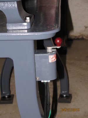
Yesterday afternoon I finished up the drum switch and completed the wiring for the motor eliminating the toggle switch in the headstock from the circuit. I mounted the drum switch on the left leg where it was when I purchased the lathe.
IMG_1050_zpspsgjiaqm.jpg

With the old motor the lathe was set up with the drum switch on the leg and the toggle switch in the headstock. I operated the lathe by selecting the rotation forward or reverse on the drum switch and turning the lathe on and off at the toggle switch. Initially, I tried wiring the new motor by splitting one of the power leads from the drum switch and routing it through the toggle switch to the motor. With the toggle switch off I switched the drum switch on and heard the motor begin to hum. However, when I flipped the toggle switch to the on position and switched the drum switch to the forward position the motor ran fine but wouldn't properly shut off at the toggle switch. This is getting beyond my electrical skills so I decided to eliminate the toggle switch for now. It was convenient to be able to turn the lathe on and off at the toggle switch on the headstock especially if I got myself into trouble and needed to switch the lathe off in an emergency. The drum switch on the leg is not as easy to get to. I'll have to investigate further to see if there is a solution. If not, I'll use the drum switch and forget about the toggle switch.

Nice looking toggle switch but I may end up removing the switch and put a plastic plug in the hole.
IMG_1052_zpsjbwupqkc.jpg

Last evening, after eliminating the toggle switch, I was able to run the lathe. After adjusting some gears for lash and adjusting the countershaft and cone pulley to center the serpentine belt I am happy, happy, happy. The lathe has never run this smooth and quiet since I have owned it. I ran it in forward and reverse, feeds engaged and disengaged, back gears engaged and disengaged, and the serpentine belt in all three positions. There was a little noise while running in back gears so I may have to reset the lash at the shifter but it is minor.

That's it for now.
 
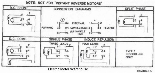
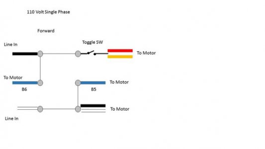
I am posting the information on my motor and drum switch in the hope someone will have a suggestion on how I can wire my motor, drum switch, and toggle switch so I can position the drum switch in fwd or rev and use the toggle switch to turn the lathe on and off.

Here's a little more info from an earlier post:
With the old motor the lathe was set up with the drum switch on the leg and the toggle switch in the headstock. I operated the lathe by selecting the rotation forward or reverse on the drum switch and turning the lathe on and off at the toggle switch. Initially, I tried wiring the new motor by splitting one of the power leads from the drum switch and routing it through the toggle switch to the motor. With the toggle switch off I switched the drum switch on and heard the motor begin to hum. Also, when I flipped the toggle switch to the on position and switched the drum switch to the forward position the motor ran fine but wouldn't properly shut off at the toggle switch and continued to rotate in a jerky fashion.

Here's the motor wiring diagram:
Motor%20Wiring0001_zpsctlfevxv.jpg

Here's the switch diagram:


Drum%20Switch%20Wiring_zpslkdemeee.jpg

Here is the diagram of how I had the wiring with the toggle switch:
Switch%20Schematic_zpsvmy9xwpx.jpg
Any input on how to wire this to make it work properly would be greatly appreciated.
 
Back
Top