Quick Measurement Of Small Taper Angle

Bob actually the sine bar was part of the first solution that had the problem of the centerline axis alignment issue. I suggested to use the sine bar for this solution simply because it has a fixed stop for the small end of the cone and the gage pins to seat against. I am sure that having the cone on a surface plate with the small end face against the inside of one leg of a ground or granite angle and the large o.d. touching the other inside leg yields the same result with the possible exception that the gage pins would not be at right angles to the cone horizontal centerline. By using a sine bar and approximating a gage stack the horizontal plane of the centerline of the cone would be closer to 90 degrees to the vertical standing gage pins and maybe that is not a issue. The key being a 90 degree angle on the inside corner of the angle plate and the gage pins, and cone equaling the large end o.d. Also are you familiar with the use of the two different dia pins a given distance apart to measure a angle as I mentioned in my previous post? I will see if I can find a example on the net. I truly am computer illiterate And as I post Randy lists one example of what I describe. Thanks Randy. When in doubt go to the Handbook! I could have saved you both some typing and head scratching. lol

Darrell
 
Darrell, That clears up the mystery. The one refinement that I saw, (and maybe missed in your explanation) would be to put a third pin under the small end of the taper to raise the axis of the taper to parallel with the sine bar. I don't think it is really necessary as any correction would be very small.

I have used pins in a similar fashion before. I never had the occasion to measure a taper mechanically. I designed a plug and mating socket system,used in one of our products, with a large diameter of .09" and a small diameter of .02" and a length of just over an inch. We had to determine a method of verifying machining accuracy and we used an optical comparator to make the measurements on the plug. The tapered end could be mounted to a cylindrical shaft so we were able to measure perpendicular to the taper axis, avoiding the problems we have been discussing. We measured the socket dimensions using precision balls. I determined the seating depth with SolidWorks (gotta love the CAD!) and wrote the spec. Our tolerance requirement the much looser than that for a Morse taper so these methods worked for us.

Randy, the machinist was the gentleman from Cupertino mentioned in post#16 and that was the part mentioned. The plug, being made fro Teflon, posed interesting challenges for QC.

I do not have a Machinery's Handbook, unfortunately. It has been on my wish list for a very long time but the tools and accessories budget is somewhat limited and it always seems to get relegated to the back of the list. The last time I had access to one was about fifteen years ago and it made for an interesting read. The fascinating thing is that most of the wisdom in that book was actually developed a hundred years ago.

Bob
 
Last edited:
...I do not have a Machinery's Handbook, unfortunately. It has been on my wish list for a very long time but the tools and accessories budget is somewhat limited and it always seems to get relegated to the back of the list. The last time I had access to one was about fifteen years ago and it made for an interesting read. The fascinating thing is that most of the wisdom in that book was actually developed a hundred years ago.Bob

Bob, you're right on target, the first edition was published in 1914. It hasn't changed much over the years either !

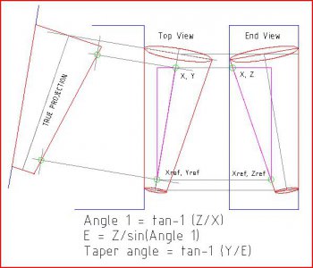
I guess I'm like a kid picking at a scab but I just couldn't let go of this taper problem (which ended up being fairly simple). Solving the taper in a milling vise would be simpler using 3-D vector analysis but the math is easier if the problem is converted to two right triangle solutions. The first triangle is the one defined by the reference, X and Z, the second is defined by the reference, Y and Z.

The X, Y and Z dimensions are obtained as mentioned previously by touching off the high points of the taper and noting the difference between the max and min values. The differences become X, Y and Z in the expression shown below.


Capture.JPG
 
Bob, you're right on target, the first edition was published in 1914. It hasn't changed much over the years either !

I guess I'm like a kid picking at a scab but I just couldn't let go of this taper problem (which ended up being fairly simple). Solving the taper in a milling vise would be simpler using 3-D vector analysis but the math is easier if the problem is converted to two right triangle solutions. The first triangle is the one defined by the reference, X and Z, the second is defined by the reference, Y and Z.

The X, Y and Z dimensions are obtained as mentioned previously by touching off the high points of the taper and noting the difference between the max and min values. The differences become X, Y and Z in the expression shown below.
I am having trouble dropping it as well. But then I'm Polish so I have a license to be stubborn. I think your explanation is along the same line that I was thinking.

One thing that bothered me was if you were trying to measure a 90 degree taper. you couldn't because the z distance would be infinite. Instead of an ellipse the section would be a parabola. I did the following drawing for my brother who is a math professor last night.
Conical Sections.JPG

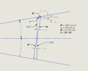
The measurement we are making is actually "l", perpendicular to the x axis. what we need is "d" because that is how a taper is defined. We can determine d from l but we need to know the angle a. Now a is the same for both the large and the small diameters so we will have enough equations but my math skills are too rusty to force a solution. Excel can do it through an iterative process, their "Solver" macro. You can pick a starting value for a based on the simple measurement or by simply guessing. I say that based on an assumption that the process is converging.
Another factor is the x distance measurement. We are traversing along an edge of the taper not its central axis so there is a 1/cosine factor; the distance along the taper axis is longer because it deviates in two directions (I'm assuming Darrell's first suggestion of placing the taper so the edge is coincident with the sine bar and the angle plate). There are two right triangle formed, one in the xy plane and one in the xz plane The included angle of both triangles is a. The actual offset of the taper axis r = sqrt(y^2 + z^2)where y and z are side opposite in the xy and xz planes. Since they are equal, r = sqrt(2)*y or 1.414*y. We now have the side opposite, "r", and the side adjacent, "x" which is our distance along the x axis the we measured when we measured our difference in z. So the taper axis distance between our measurement points, D = x/cos(arctan(r/x)). arctan x is the angle of the resultant vector from the y and z offsets. So we should have all we need to calculate the two diameters.

This is all very complicated and it addles my brain so I won't guarantee that I haven't made a mistake in logic or in math. It's a good thing that I like puzzles. I'm told it keeps me from getting senile.

Darrell's proposal of using the gage pins is actually a simpler way to accomplish the task although I can see a potential problem with trying to balance all those components and making a measurement with a mike as well. Another drawback is you really need a double set of gage pins , preferably by tenths, to make the measurement. However, the setup guarantees that you are measuring perpendicular to the taper axis, as required. Your original method with the 123 block accomplishes the same thing. The only drawback is it requires a flat perpendicular to the taper axis. OxTool's dual diameter cylinder method does the same as you can align the cylinder to be parallel to the taper axis. The drawback with his method is you have to be able to measure the diameters accurately. Being an inside measurement, it will be some sort of transfer measurement like gage pins. This introduces an additional error source into the measurement. One possibility would be to "calibrate" the cylinder using a known taper. Based on the standards requirement that I state much earlier, that is actually a pretty good solution. If the taper is stood on it's large end on a flat surface and a height gage is used to measure , the OxTool method is essentially the same as your 123 block method.
 
  • Like
Reactions: 18w
Bob, just got back to this. I was hoping that you might check my (I'll call it a hypothesis rather than a solution) math graphically. You are obviously skilled and FAST at CAD and I am as sluggish as molasses in the morning. It took me most of the afternoon just to draw the taper above, LOL.

...Your original method with the 123 block accomplishes the same thing. The only drawback is it requires a flat perpendicular to the taper axis...

That is a problem and addressing it is only slightly less difficult than aligning the taper axis horizontally if using the mill table + DTI method. KD4gij mentioned bench centers and that would solve ALL of the problems if the taper had concentric center features at both ends. Maybe if the bench had female centers at each end - well that has it's own set of problems ...

Placing the small end of the taper in a hole in the measuring surface base (for the 1-2-3 block measurement) and aligning it - as much as possible - perpendicular to the measuring surface could be helpful to measure tapers that do not have one flat, axially perpendicular end. But this would result in errors in the minimum and maximum diameter measurements due to angular misalignment.

I wonder how much error would result if the taper was carefully aligned visually to be perpendicular ? The diameter measurements would be elliptical ... one could make another diameter measurement, 90 degrees to the first and average the two readings. But this presumes that the taper is fixed in position - more complication !

The old-timers MUST have addressed this problem in a practical manner that doesn't include any electronic device ... I can't believe that there isn't a simple way to do this :)

Using the mill table, one could block up one side of the taper, as I think you and Darrell were suggesting with the pins. By sweeping from end to end, finding the high points, it would be possible to align the taper axis with the table travel.

Maybe with a "tenths" indicator this would be adequate. Obviously, if the taper axis is aligned, the measurement is a piece of cake, LOL. Somehow, however, this doesn't suggest the "elegance" of a true geometrical solution.
 
  • Like
Reactions: 18w
Bob, just got back to this. I was hoping that you might check my (I'll call it a hypothesis rather than a solution) math graphically. You are obviously skilled and FAST at CAD and I am as sluggish as molasses in the morning. It took me most of the afternoon just to draw the taper above, LOL.


That is a problem and addressing it is only slightly less difficult than aligning the taper axis horizontally if using the mill table + DTI method. KD4gij mentioned bench centers and that would solve ALL of the problems if the taper had concentric center features at both ends. Maybe if the bench had female centers at each end - well that has it's own set of problems ...

Placing the small end of the taper in a hole in the measuring surface base (for the 1-2-3 block measurement) and aligning it - as much as possible - perpendicular to the measuring surface could be helpful to measure tapers that do not have one flat, axially perpendicular end. But this would result in errors in the minimum and maximum diameter measurements due to angular misalignment.

I wonder how much error would result if the taper was carefully aligned visually to be perpendicular ? The diameter measurements would be elliptical ... one could make another diameter measurement, 90 degrees to the first and average the two readings. But this presumes that the taper is fixed in position - more complication !

The old-timers MUST have addressed this problem in a practical manner that doesn't include any electronic device ... I can't believe that there isn't a simple way to do this :)

Using the mill table, one could block up one side of the taper, as I think you and Darrell were suggesting with the pins. By sweeping from end to end, finding the high points, it would be possible to align the taper axis with the table travel.

Maybe with a "tenths" indicator this would be adequate. Obviously, if the taper axis is aligned, the measurement is a piece of cake, LOL. Somehow, however, this doesn't suggest the "elegance" of a true geometrical solution.

I think that you are correct in the assumption that visual alignment will suffice. The cosine error will be quite small. A 1 degree error is quite huge visually and that creates a cosine error of 150 ppm. We cannot practically make distance measurements to that kind of accuracy. O f course the errors can stack, but even so, measuring a diameter difference of .1 inches more or less to +/-.1 mil is 1000 ppm..

I really would like to find out how the" big boys" do it and it would be very interesting to see how it was done a hundred years ago.

I did find an excerpt from "Machine Shop Practice, vol. 1" which places the taper between horizontal centers and uses a 10" sine bar to measure the taper. They also show a method using four identical pin gages. The the small (perpendicular) end of the taper is placed on a surface plate and the pins placed on the plate on either side of the taper. Two identical gage blocks are placed outside of the pins and the second set of pins placed on either side of the taper. The outside to outside distances of the two sets of pins are measured. The vertical distance between the two sets is well know. You now have the diameter difference and the distance difference. The gage blocks can have a tolerance of +/- 4 ppm; the gage pins, .04 mil and the mike .05 for a maximum error of .1 mil on each diameter measurement. If the diameter difference is about .1", this will give you a possible error in the taper of about .4 minutes of arc. This probably as good as we can expect without more sophisticated metrological tools.

Bob
 
Bob, thanks for referring to the Machine Shop Practice excerpt. That is a simpler version of what I was trying to describe as my example is sometimes difficult with out 3 hands or lots of clamps and magnets. But that is a picture of a similar way of doing it. I offer up as to how the big boys do it, possibly a optical comparator or now the more popular CMM?

Darrell
 
In another time and place, I was given an "instrument lathe" with an unknown
taper. Being slow in trig, I resorted to the business card method, using sharp scissors. Chopped up cards to get a close fit, drew a sharp centerline and two
closely measured verticals, used calipers to transfer diameters to stock in other
lathe, hog and file to,measurements, blue female taper, and finish. S impler than it sounds.......BLJHB
 
As I read the impressive math and metrologic presentation above, I see that (no
original thought from my addled brain , Pythagoris could not work in free space,
and at the very summit of Machining,we,too must visualize and file to fit. Thanks,
.........BLJHB.
 
Back
Top