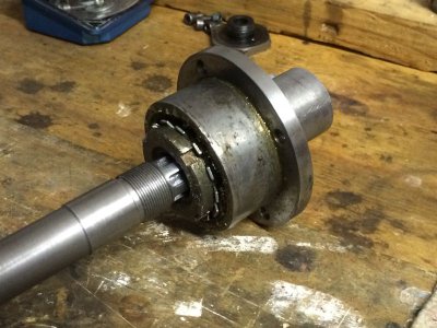
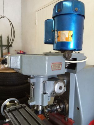
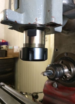
Mill Collet Holder Attachement

Did some digging and came across this method of straddle milling the splines which made sense to me as you form both sides of the tooth in one pass, then just tidy up the bottom of the groove.
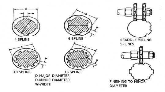
4-40.jpg

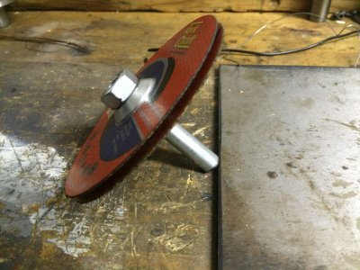
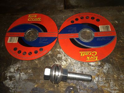
I don't have two similar size slitting saws but thought I could do the same thing with two angle grinder disc. So I made up a shaft and spacer to hold the two disc the required distance apart - also turned up a dummy shaft to practice on as I didn't want to experiment on the spindle.
IMG_1239s.jpg

Turns out the 1mm disks are not ridged enough and flex too much. 3mm discs were not much better and the 'tooth' tended to get wider as the spline got further up the shaft - so a failure. May of worked if the spacer in the middle and the collars on either side had been larger in diameter, like 90% of the disc diameter to provide more support, but it still appeared the disc were wearing unevenly so the sides of the tooth became less vertical over time .

So it was a fun day in the shop but not very productive in the end - and back to the idea of milling each slot with three passes. IMG_1241s.jpg
 
You're on the right path, the abrasive disks were a good idea, just didn't pan out. Slitting saws are available on Ebay for not too much, I'm not sure about milling cutters, I haven't needed any, so haven't looked.
 
The other alternative I found is to grind a tool to the required groove profile and used it in a flycutter to make the groove.
In my instance (shaft size, number of splines) the tool would simply be a 60deg angle (like a threading tool), with the point blunted off until its about a 2.7mm flat. At the top of the groove the tool would only need to me 4mm wide so I would have HSS blanks around (or old threading tools) I could used. Only concern is at full depth the total cutting edge would be about 7mm (2mm for the side of each tooth and about 3mm for the bottom), and an interrupted cut, which could be a bit hard on the mill.

Horizontal mill is a 3/4hp motor with an ISO30 spindle and some pretty heavy belt pulleys (two stage speed reduction so two sets of heavy pulleys and plenty of inertia - I can't even used the highest speed ratio as the workshop circuit breaker trips before it can get up to speed)
 
Could you rough out 3 mm grooves with an end mill or keyway cutter and then finish with the flycutter?
 
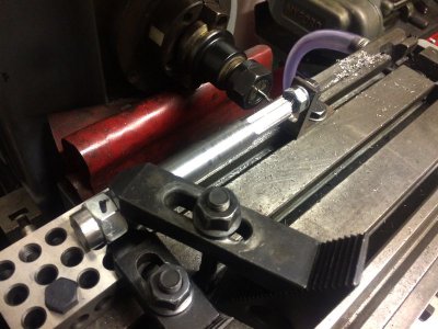
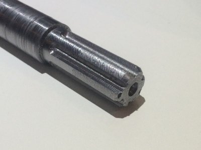
After knocking up a simple dead center for my mill table and a bit of playing around I managed to cut a workable spline in a dummy test shaft using my Nut Indexer.
Just did two passes and made the cuts deeper that needed so the slots are the correct width, but deeper that required - I figure the sides are the important surface as these are where the power is transmitted and the correct OD of the spline will stop any 'slop'.
Tomorrow the real thing.

IMG_1251s.jpg

IMG_1252s.jpg
 
Last edited:
Excellent. I also applaud the use of aluminum to make a sample part.
 
Excellent. I also applaud the use of aluminum to make a sample part.
That would of been a good idea - but I'm not that smart, it's just a steel offcut of the same material I machined the spindle out of.
 
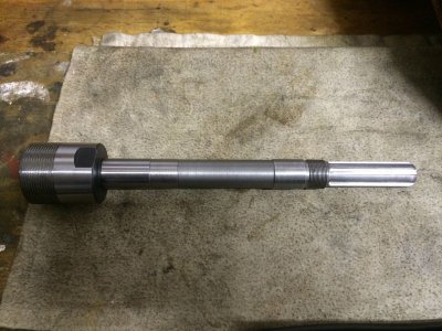
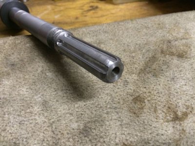
Well I bit the bullet and milled the spline on the spindle shaft today - and it worked out perfect if I do say so myself.

IMG_1255s.jpg

IMG_1257.sjpg.jpg

And most importantly it fits beautifully with the female spline

IMG_1261s.jpg

I didn't have time to re-assemble the quill, so that will probably be during the evenings next week and then the final test as to what run out I get.

Thanks to everyone for their comments and suggestions .
 
Well I reassembled the quill and it work great except for one small problem - it's too short.

I did know this may be a problem as at one stage during the machining I had to face off the centre drill hole and re-drill it to correct the centre. I had hope the loss of 5mm wouldn't be a problem, but wouldn't you know it when the quill is fully extended the male and female spline just disengage. I don't normally use the quill travel anyway and typically have it locked in the upper most position to avoid the tool being pulled into or pushed out of the work - so it is perfectly usable for now and the Mark II spindle will correct any defects (I had already ordered a ER32 collet chuck with a 200mm x 20mm dia. shaft which will allow the stock shaft to span both bearings). Gives me more chance to practice me spline milling .

Measured run-out at the chuck taper of 0.04mm - so with a home made spindle and reusing the old bearings I was pretty happy with that (I brought new bearings but decided to save them for the Mark II and just cleaned and repacked the old ones this time)

IMG_1291s.jpg

IMG_1293s.jpg
 
Great work Pete, talk about thinking outside the box for a perfect solution. Pardon the novice question but, when you used the nut to index the shaft for splines, how did you attach it to the part to be sure that it would not move (turn) and screw up the indexing ? Thanks JR49
 
Back
Top