VN Work Continues On My Vn #12

That baby sure looks great. Your doing a really nice job on the refurb. You must be gettin antsi I know if I was this close to being finished I'd be . Good job
 
I actually have 2 now, I got to get this done so I can sell the 2nd. Plus, I am running out of good painting days, and I have a whole bunch of other things to do.
 
Jason,

Looking good!

I don't see the permanent feed stops on the table. There should be a tapped hole in the slot on either side for the permanent stops. Idiot operators will remove them to get a little more travel and if you feed the table into the right hand-wheel bracket you will break it. Do you have the release mechanism somewhere?

Cal
 
There are a lot of pieces in various states of refinish. Yes, I have that piece.

Jason
 
Cal,

Good point. Have seen this reference several times. My unit does not have the hard stops either, and not sure what they look like. Any good photo/dimensions to be able to make some? My adjustable t-bolt just has a spacer hanging off the end of the bolt, so a photo of what the adjustable stop looks like might be useful as well.

Ron
 
Finished painting tonight. Should be back together an done next weekend.

IMG_20150908_194242328.jpg
IMG_20150908_194250117.jpg

Jason
 
Cal,

Good point. Have seen this reference several times. My unit does not have the hard stops either, and not sure what they look like. Any good photo/dimensions to be able to make some? My adjustable t-bolt just has a spacer hanging off the end of the bolt, so a photo of what the adjustable stop looks like might be useful as well.

Ron
Ron,

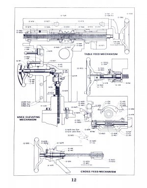
I can't find the set that I have, but I've attached a drawing that shows the movable and right-hand stops. The left stop is the mirror of the right. I don't think that there's anything too special about any of the dimensions, as long as they work.

Does your machine have tapped holes in the slot for the fixed stops?

Cal

VN12_12.jpg
 
Cal,

Thank you for the drawing. Helpful for a number of reasons, as my unit is missing the left hand table feed handle and accompanying items. Makes it interesting when trying to advance a known distance. My right side is a kluge as well, but at least has a crank.

I seem to recall there being tapped holes in the slot, near the ends. I have an adjustable t-bolt, but it just has a round tube on it. I get the idea from the drawings, and will try to figure a scale to get close to the actual size. Another opportunity to use the machine to make parts!

Speaking of which, in trying to get the feed gearbox cleaned up I managed to break the only semi-working shift lever (it was bent), so that I will need to make two shift levers. I did score a small 3-phase 1/4 HP, Frame 56 motor that looks like it will fit.

Working on making the peg end feather keys for the UHS head sliding gear, as well as the coupling links for the feed system. Breaking in my new rotary table, and have shown proof of concept to make the peg. Just need to schedule enough time to complete the chore. My machine is located miles away in the blacksmith shop at a museum, and try not to have the machine uncovered when there are fires going. Nasty coal smoke and grit.

Ron
 
Ron,

Send me an e-mail and I'll get you the rest of that manual.

Nelson parted out a No. 12 a year or two back. See if he has any of the parts that you need for the feed dial, etc.

Cal
 
Back
Top