- Joined
- Dec 29, 2012
- Messages
- 394
For a tailstock to be aligned properly for precision work on the lathe 3 conditions must apply:
A. The tailstock must be aligned parallel to the bed, so the quill runs true to the longitudinal axis of the machine.
B. The tailstock might be parallel to the bed but not in axial alignment with the headstock. So it must also be in alignment with the headstock. If you are using the tailstock to turn something, a misalignment of 0.1 mm between headstock and tailstock will cause a difference in diameter of 0.2 mm between the two ends of the workpiece.
C. The tailstock might be parallel to the bed, in axial alignment with the headstock, but its centre is on a different height from the headstock. It also must have the same height with the headstock’s centre (vertical alignment with the headstock).
A. Making the tailstock parallel to the bed
My mini-lathe’s tailstock has one setscrew on the right hand end, which does not permit axial adjustment of the upper part.
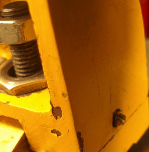
This is really a drawback, especially since nothing seems to be machined quite true on my lathe.
To make things worse, the upper and lower parts of the tailstock are secured together by a screw underneath the tailstock (marked “1” in the following sketch), so even if you manage to get everything right, you cannot tighten the locking screw to secure the two parts together.
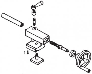
There are two modifications to solve the problem. The first is to replace the locking screw with a bolt which can be tightened from above.
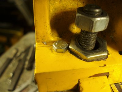
This involves drilling out the threaded hole in the upper section of the tailstock, and using a bolt which goes right through from the top, and is fitted with a square or oblong nut that cannot rotate in the slot in the underside of the tailstock. Tightening the bolt from the top locks the two parts together.
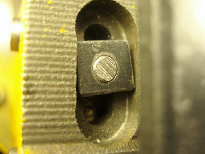
The second modification involves drilling and tapping two more holes in the left hand end of the upper section, similar to the one that is already in the right hand end.
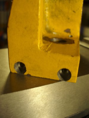
The flange in the lower section is thereby sandwiched between three adjustment screws. To alter the angle of the tailstock (A) back off the screw on the right side very slightly, and tighten the corresponding screw on the left side the angle changes. When you’ve finished, make sure that all three screws are equally tight.
B. Make tailstock parallel to the headstock
Once the tailstock's parallelism to the bed is correct (checked with a DTI), the lateral alignment (B) can be adjusted roughly by loosening the screw that holds the two parts together, backing off the screw on the right hand end, tapping the headstock lightly (either from back or front side) to move it, and then retightening the loosen screws.
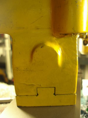
A more sophisticated approach involves adding an adjuster mechanism to the back of the tailstock like the one below.
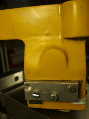
With the mechanism lateral alignment is achieved by turning the central screw which acts against the top section and moves it quite precisely.
C. Adjust the tailstock height
The only way to adjust height of the tailstock is if it is higher than the headstock to mill it, or, if it is lower than the headstock (as in my tailstock) to add shims (thank you soda can) as photo below.
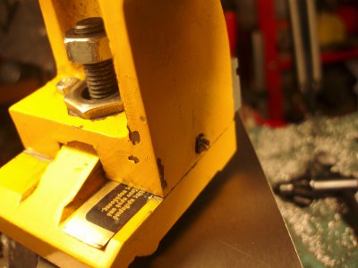
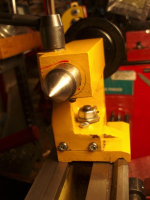
Modified tailstock on the lathe ready for precision work.
Thank you for reading this
Petros


A. The tailstock must be aligned parallel to the bed, so the quill runs true to the longitudinal axis of the machine.
B. The tailstock might be parallel to the bed but not in axial alignment with the headstock. So it must also be in alignment with the headstock. If you are using the tailstock to turn something, a misalignment of 0.1 mm between headstock and tailstock will cause a difference in diameter of 0.2 mm between the two ends of the workpiece.
C. The tailstock might be parallel to the bed, in axial alignment with the headstock, but its centre is on a different height from the headstock. It also must have the same height with the headstock’s centre (vertical alignment with the headstock).
A. Making the tailstock parallel to the bed
My mini-lathe’s tailstock has one setscrew on the right hand end, which does not permit axial adjustment of the upper part.

This is really a drawback, especially since nothing seems to be machined quite true on my lathe.
To make things worse, the upper and lower parts of the tailstock are secured together by a screw underneath the tailstock (marked “1” in the following sketch), so even if you manage to get everything right, you cannot tighten the locking screw to secure the two parts together.

There are two modifications to solve the problem. The first is to replace the locking screw with a bolt which can be tightened from above.

This involves drilling out the threaded hole in the upper section of the tailstock, and using a bolt which goes right through from the top, and is fitted with a square or oblong nut that cannot rotate in the slot in the underside of the tailstock. Tightening the bolt from the top locks the two parts together.

The second modification involves drilling and tapping two more holes in the left hand end of the upper section, similar to the one that is already in the right hand end.

The flange in the lower section is thereby sandwiched between three adjustment screws. To alter the angle of the tailstock (A) back off the screw on the right side very slightly, and tighten the corresponding screw on the left side the angle changes. When you’ve finished, make sure that all three screws are equally tight.
B. Make tailstock parallel to the headstock
Once the tailstock's parallelism to the bed is correct (checked with a DTI), the lateral alignment (B) can be adjusted roughly by loosening the screw that holds the two parts together, backing off the screw on the right hand end, tapping the headstock lightly (either from back or front side) to move it, and then retightening the loosen screws.

A more sophisticated approach involves adding an adjuster mechanism to the back of the tailstock like the one below.

With the mechanism lateral alignment is achieved by turning the central screw which acts against the top section and moves it quite precisely.
C. Adjust the tailstock height
The only way to adjust height of the tailstock is if it is higher than the headstock to mill it, or, if it is lower than the headstock (as in my tailstock) to add shims (thank you soda can) as photo below.

Modified tailstock on the lathe ready for precision work.

Thank you for reading this
Petros


Last edited:

