Clausing 5418 Lathe

Good mroning - in the process of taking apart the compound in this lathe I discovered that one of the T-bolts in the compound rotaion mechanism is stripped. I managed to get it out but I need to replace it. I have a question into Clausing but thought I'd check to see if anybode had 1 oir 2 of these as extras that they would like to move along. It is clausing number DL-475. I did find a close one at Rocklet but it would take some "reshaping".

Thanks
Rick
 
First off nice work Rick. LO spindle sizehttp://www.lathes.co.uk/latheparts/page9.html My Colchester is LOO for a spindle bush I got a 5>3 MT adapter and cut the tail off till it fitted I bearing blued the inside of the spindle to check the fit was good it was so it may be the same on yours I have yet to cut the outboard end off. There was a step in the spindle bore that interfered with the fit hence having to keep cutting it down
 
Minor point - that's L0 and L00. A Loo is another name for a toilet, latrine, outhouse or privy. :tranquility: People commonly make the same mistake with one of the Atlas mill models. It's actually an M1 (or M1A, etc.). But often get's written as MI (or MIA, etc.).
 
Thought I'd give an update of progress.
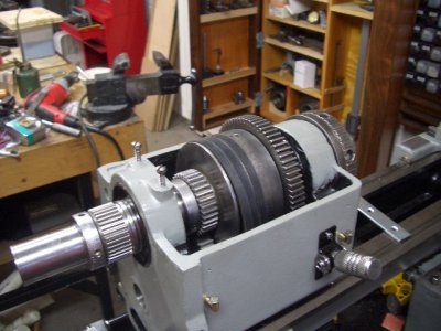
Spindle - all of the spindle pieces and parts are cleanded up and ready to assemble - just waiting for the back gear to arrive (in the mail). Regarding the spindle taper question I had - Clausing never did respond but I got a 4-1/2 to3 MT adapter and it fit very nicely. It sticks out the end of the spindle a bit but the taper is correct.
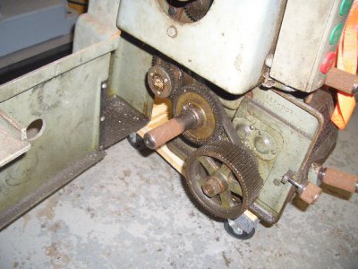
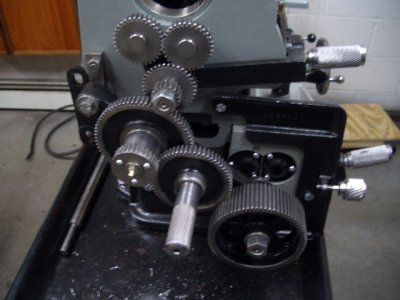
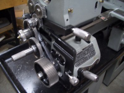
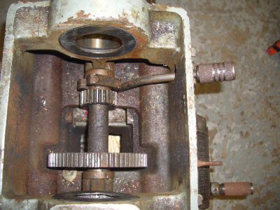
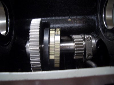
Gear Train - All of the gear train components are cleaned up and installed. Of course I'll have toi take them back out to install the back gear.

Lathe HS Gear Train.JPG

QC Gear Train small 1.JPG

QC Gear Train small 2.JPG

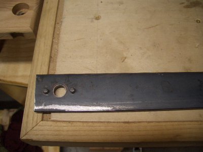
Saddle/Cross slide/Compound - All of these components are cleaned up, painted and ready to re-assemble. Right now I'm struggling with the compound take up nut so there may be questions to come :). I had two problems in this area - the first was a strippped T-nut in the compound swivel mechanism. Clausing wanted $26 plus shipping for the T-nut so Idecided to try a standard 5/16 X 1" T-nut from Rockler. It fit pretty well but was a little long so it required some twisting/turning to get it by the access slot and then it was difficult to get back out. A few passes on each end at the grinder and it fit perfectly and functions as expected. The other problem I had previously mentioned was getting the nut off that holds the lead screw in place on the compound. This required a pin type face spanner wrench that I didn't have. Thanks to the encouragement here I was able to fabricate one using 1-1/2 X 1/4 flat bar and dowel pins provided by another member (Thanks Andy). I put a clearance hole that slipped over the lead screw and used a spacer and nut to keep the spanner in place. Worked very well.

Spanner.JPG

Taper Attachment - 90% disassembled and cleaned up - there is one componet that I may have questions on - more later. The only problem I ran into was a bent adjustment screw that prevented the screw from easily turing in it's brass nut. clausing wanted $72 plus shipping for that part - so I decided to straighten it. It now turns through the brass nut. If it turns out to be a problem at least I know I can get one from clausing if I have to.
I guess that's all for now.
Rick
 
Hi Rick,

Looks beautiful! Very nice job! I'm sure you're anxious to make some chips!

Bruce
 
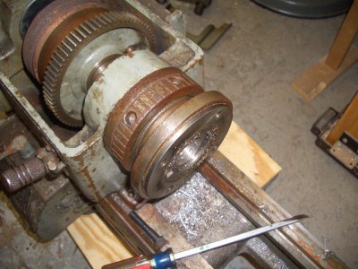
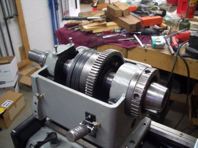
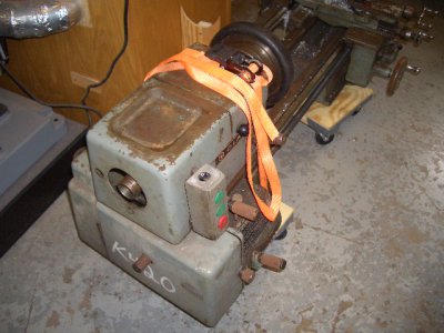
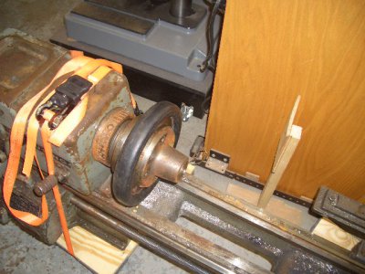
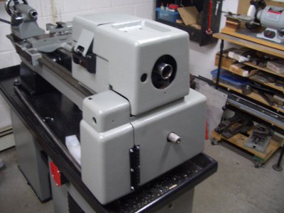
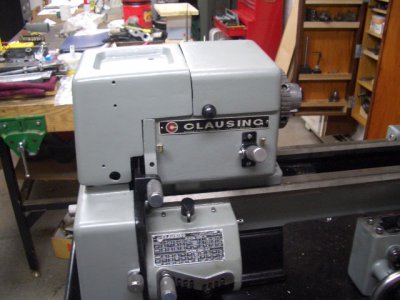
Time for a progress report - the headstock is complete and covers are installed. Here's a few before and after pics
Back gear (the large gear is new)

Back Gear Assembly.JPG

Back Gear Complete.JPG


Spindle

Spindle - Chuck Removed.JPG

Spindle Assembled Front.JPG

Spindle Assembled Rear.JPG


and the covers installed

Lathe HS.JPG

Lathe HS 2.JPG

Covers Installed Front.JPG

Covers Installed Rear.JPG

A few minor details remain - I'm missing the bumpers that go on the pivoting spindle pulley cover, the decals for the back gear in and out positions and of course the electrical box. Also - lots of work to do on the cross slide/taper attachment yet.
Thanks for looking
Rick
 
Hi Rick,

Looks really nice. Bet you're almost hesitant to use it and get it dirty!

Best regards, Bruce
 
Hey Bruce - yep that first time with oil all over the machine is going to be tough :). I'm in the process of getting the wiring done but needed to order a 18-7 cable for the vfd controls so I'm waiting again. In the meantime I started reassemblingand tryingto understand the taper attachment. I discivered I am missing afew parts - specifically the bed clamp parts. I'm guessing it will be a long shot to find them. I did send Clausing a message to see if they have them. Other than that I probably will have a tough time finding them.

Rick
 
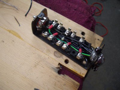
Its alive!!! I got the control station wired up today using an 18-7 cable. This is an AB station with three switches - all momentary (2 NO and 1 NC).

Control Station Internal Wiring.JPG

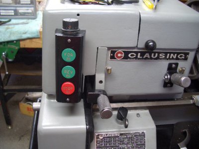
As I described previously - the control station had a knockout at the top that was not going to be used so I took advantage of that and mounted the potentiometer in that position. The mounting was pretty straight forward - rubber washer between the potentiometer and inside of the box, metal washer on the outside of the box and a nut to hold everything in place. The only obstacle was that the potentiometer didn't come with a standard panel nut and the stem has a M10-1 thread. Rather than spend time trying to locate a panel nut with those dimensions I used a standard metric hex nut. It was too tall and I couldn't get the operating know on far enough so I simply put the nut in the milling vice reduced the thickness byhalf with an end mill.
Picture of the control station mounted

Control Station 1.JPG

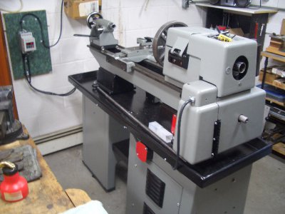
finally - I didn't want a bunch of cables dragging around at the back o fthe lathe so I routed them under the chip tray lip and used some plastic spacers with #10 screws through a drilled and tapped hole in the lip. does a good job of keeping the cables off the floor and out of the way.

Wire Routing.JPG

I wanted to get the VFD up in the air more but unfortunately what I thought would be enough cable was not even close.
Thanks for looking
Rick who is moving on to the taper attachment
 
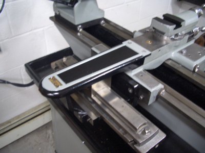
I haven't spent much time with the lathe in the last week due to chasing around a solution for the taper attachment missing pieces and the unseasonably mild weather that allowed me to catch up with the falling leaves. However I did manage to get a few things done - apron/saddle/compound/taper attachment installed
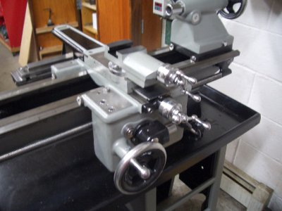
Saddle_Apron Front.JPG

Saddle_Apron Rear.JPG

I also created a speed chart for various data points between the step pulley settings and the VFD frequency. I then tested the lathe operationally - it seems everything is working in terms of the gear train, reverse lever and power feeds as well as the half nuts. I did document a number of areas that I am concerned with - i decided to list them all here in case anyone sees some potential common symptms of a deeper cause.
1. Speeds are running high at all data points. In direct drive they are 5 to 7 percent high except for pulley step 2 (next to lowest speed) - that is running 14% high. In back gear the sppeds are 5 to 12 percent high - again except for pulley step 3 which is running 16% high.
2. Counter shaft to spindle belts are tight - no more adjustment available.
3. Spindle pulley has some slight movement around the back gear plunger pin
4. Noticeable noise/clunk when running with just the spindle pulley - back gear OUT and pulley not engaged to back gear via the plunger pin.
5. .001" up/down movement of the spindle at the head stock end. none at the outboard end.
6. Back gear noisy - I have some adjustment on the gear mesh but am not sure what the "correct" mesh should be
7. Vibration starting around 650 RPM - enough that i can feel the lathe bed vibrating
8. Sliding gear hard to move in and out - this has a steel ball/spring detent with no adjustment
9. Gear train noisy - I have not tried any lubrication directly to the revers gears yet.
A number of the above are probably nuisance issues or the nature of the beast (noise). My biggest concern is the vibration.
I'm wondering if there is some interaction going on between tight belts/pulley alignment/spindle play. I know thebekts are tight becasue I am out of movement for adjusting and the belts are very close to the front of the head stock casting where they come up through from the cabinet.
Before I replace the belts (which requires pulling the spindle/back gear and countershaft) I'm wondering if any one has some thoughts on these issues. The other issues are liveable/can be delayed to a future effort.
Thanks
Rick
 
Back
Top