[Metrology] Mill Spindle Mounted Microscope (aka Cheap Optical Comparator)

Bob,

Your app is pure genius! Many many thanks for sharing it with the machinist community.

Regarding the comparator function, would it be feasible to perhaps build a split screen ( or overlay function) and use dual spindle mounted cameras to create a comparator function? One spindle would be mounted and centered on the quill as you have already described - delivering an image of the work piece. The other camera could be mounted on a second position on the spindle mount, or perhaps independently of the quill, say on a separate dial indicator stand or other vertical post at a nearby location, and render an image layers of a known reference object - for example a radius gauge. Then the two images could be compared and overlaid to determine goodness of fit. Is this set up feasible??

I could see where two different focal lengths might be a problem. However in Geographic information systems, when one registers separate data layers with a known projection and coordinate extent, they always overlay at the same scale and relative extent. I image something similar perhaps could be worked out with two camera settings?

Another step would be to find a video camera with a wifi chip and do away with the USB cord entirely...

Thanks again for developing such a superb app. I can't wait to build up a mount and try it out!

Regards
Glenn
Glenn, The app is pure genius but the all the credit goes to Jim Dawson. It was he that volunteered to develop the app and has put in all the effort in adding features.
 
Regarding the comparator function, would it be feasible to perhaps build a split screen ( or overlay function) and use dual spindle mounted cameras to create a comparator function? One spindle would be mounted and centered on the quill as you have already described - delivering an image of the work piece. The other camera could be mounted on a second position on the spindle mount, or perhaps independently of the quill, say on a separate dial indicator stand or other vertical post at a nearby location, and render an image layers of a known reference object - for example a radius gauge. Then the two images could be compared and overlaid to determine goodness of fit. Is this set up feasible??

I could see where two different focal lengths might be a problem. However in Geographic information systems, when one registers separate data layers with a known projection and coordinate extent, they always overlay at the same scale and relative extent. I image something similar perhaps could be worked out with two camera settings?

Another step would be to find a video camera with a wifi chip and do away with the USB cord entirely...

Thanks again for developing such a superb app. I can't wait to build up a mount and try it out!

Regards
Glenn
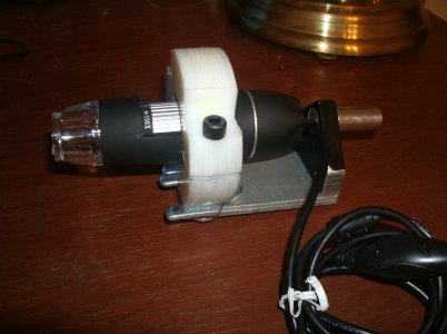
Regarding the comparator, my objective in making the mill mounted microscope was to use the x-y table coupled with the DRO to create a precision mechanical stage. With the crosshairs, I can position on one feature, record the position, and move to another feature. My mill DRO is more accurate than I could hope a visual comparator to be.

Projected comparator standards pose a problem in that you need to precisely know what the magnification is if you want accurate measurements. The original software supplied with the camera has a workable calibration routine, although it is post processing on captured images.

With Jim's existing app, you can calibrate it with the movable crosshairs and supplied calibration scale. Center the crosshairs at one point on your calibration standard and note the pixel location. Move to the second point and note the pixel location. A little geometry will give you the separation distance in pixels and you now have a calibrated screen. Now repeat the the process on your target and you have made your measurement.

The limitation, of course, is that both ends of the object have to be in the field of view. By using the mill DRO, I can make measurements to a few tenths of thousandths precision over the travel range of the mill which, in my case, is anything within a 7.3" x 14.4" area.

Regarding going wireless, it could be done fairly easily by using an Arduino microcomputer. My lathe DRO communicates with my smart phone via Arduino based Bluetoth. Raspberry PI just announced the $5 Raspberry Pi Zero which would also be a candidate for the interface.

Bob
 
Bob and Jim,

I apologize for missing Jim's software contribution! Both you guys deserve three Huzzahs for bringing this to life!

When you mentioned comparator, I was thinking of the optical comparator's that one finds near grinding rooms - that allow you to overlay tooling you have made up with known shapes to determine how closely your tool geometry fits the required shape or angle...

I could image your device and software would be perfect to check for roundness, actually any kind of complex geometr and 'straightness' of edges of a taper all along the length of the work! Can't wait to try to make one these devices and try it out.

I will look for the Bluetooth interfaces you mentioned.

Thanks much!

Glenn
 
The camera and Jim Dawson's app works fine in my laptop with Win10. Thank you Jim !
 
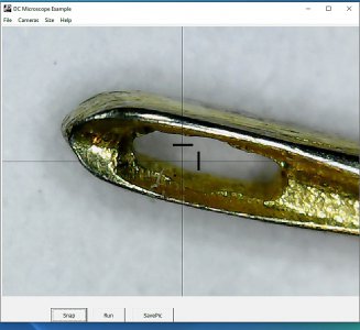
Here is an idea in case you will revise the software at some time in the future. It would be great to have some form of distance reference near the cross-hair. Like e.g. one vertical and one horizontal mark 0.1 mm from the cross. Or perhaps a circle.

Thanks again for a great feature. I also like that the picture can be scaled. This wasn't possible for me with the original software. It didn't respond to resolution selections.


Needle eye.jpg
 
Here is an idea in case you will revise the software at some time in the future. It would be great to have some form of distance reference near the cross-hair. Like e.g. one vertical and one horizontal mark 0.1 mm from the cross. Or perhaps a circle.

Thanks again for a great feature. I also like that the picture can be scaled. This wasn't possible for me with the original software. It didn't respond to resolution selections.


View attachment 115981
An absolute distance reference isn't possible due to the variable magnification. The bullseye pattern, if pre-calibrated, could be used as a reference. Set the size to a minimum and use the calibration sheet that came with the microscope or a pair of calipers as a standard. If you don't change the magnification on the microscope, you should have your reference.

From your photo, it looks like you are using an earlier rev. Download the latest (rev. 5, I believe) found earlier in this thread and install.
 
Actual, GIS software and I think CAD routinely provides distance measurements at any scale (magnification) for all kinds of digital shapes- circles, polygons, lines etc. both areal measurement and linear distance measurement.

I wonder if there may be open source libraries available that might be imported to accomplish this function? I suppose the problem lies in establishing an initial datum regarding the workpiece-e.g. How long is an "inch" or other unit of measurement in the camera's viewing screen...

What would be cool is if you could draw a circle around the edge of a hole and the software would display the diameter.
 
Back
Top