New To Me 1928 South Bend Junior 9"

Forgot to add, I ordered a set of four of these leveling feet:
http://www.mcmaster.com/#63965K67

Also put in an order with blue chip machine shop for some A/B/C oils.

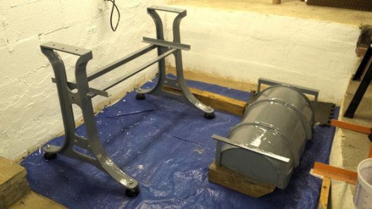
The cast iron legs are primed and hopefully will be able to finish working on their paint the rest of this week/weekend.
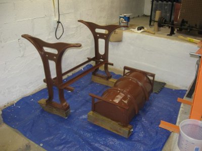
IMG_2512%20(Small).JPG

I did not get the South Bend wrenches with the lathe so I would like to find those, an MT2 taper drill chuck for the tailstock, etc.

It is looking great! You have access to things I can only dream of. I have to settle with single phase, 110v, and the cheapest way forward is the 1725 rpm a/c motor I am trying to get connected.

You are also correct. For a 1725 rpm motor, you will need that 10" pulley. The counter shafts had something similar in size that was driven by the motors, which was also usually an a/c motor at the time. The original motor was a 1/3 hp motor. The big factor is the flat belt pulley size, and the cone pulley size. If those are equal, the ten might not be enough with a 1725 rpm motor. If you can do a variable speed motor, that's what you want. I think I tossed something on that website that had a pulley size calculator and would tell you the spindle speed, with a counter shaft.


Sent from my iPad using Tapatalk
 
Small updates. Fired up the old washing machine motor and verified it is an 1800 RPM motor, however the bearings are shot in it, and it clearly just isn't the right thing. So will be continuing down the DC motor replacement path.

Have been thinking about how to mount the countershaft and deal with belts.

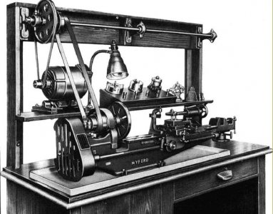
Searching through Google images for lathe countershafts I ran into this, and I think will use this as a basis for my setup:
img7.jpg

My plan is this:
Purchase one 10' section of SUPERSTRUT 1-5/8-in x 1-5/8-in Gold-Galvanized Half Slot Channel Strut and a few 3/8 spring nuts from Lowe's. Cut strut in half and mount the two 5' sections vertically on the concrete block wall vertically, a few feet apart. Then I will use something like a 2x6 to span the two vertical strut sections in a horizontal fashion and bolt through to the nuts. I will mount the countershaft to the top 2x6, using my wood router to slot the mounting holes for the countershaft horizontally to allow for alignment adjustment. Once the lathe is in place, I will install the belt and raise the top 2x6 and tighten it to the strut to set the belt tension. The bottom 2x6 will have the motor mounted, likewise with horizontal mounting slots for adjustment. After the top 2x6 is set and first belt is tensioned, I will pull the second 2x6 down and tighten to the strut to set the belt tension between motor and countershaft. By using the strut solution I can easily adjust either belt tension later, and the cost to install is minimal.

The old washing machine motor has a 2.25" OD flat belt pulley with a reducing bushing to about 3/8" shaft. I need to work on getting this off the motor and the ID of the bushing opened up to 5/8". If only I had a lathe ;-)
 
That's where I got lucky. I had a 1942 Dunlap wood lathe (534.0601) with a metal attachment (basically, a cross/compound slide assembly that bolted to the ways - no lead screw). That let me do some cutting and facing on some parts that brought the South Bend to life. Now the Dunlap can go back to being just a wood lathe, but it definitely assisted in the metalwork side of life.

Note, you can make wooden parts that will temporarily work using a drill press, or even a portable drill (cordless or otherwise) and chucking the "work" up. David Gingery showed some of this in his books about building things from "scrap", using a wooden pulley to turn a better metal pulley.
 
A bit more progress.

Finished painting the legs and "chip pan", and installed the leveling feet:
20161002_205116%20(Small).png

Going back and forth on the countershaft some more. I decided to go with a V-Belt between motor and countershaft, and ordered a 10" 4L sheave with 7/8" bore for the countershaft as well as a 1/5" 4L sheave with 5/8" bore for the motor. Bought an adjustable motor base for the motor.

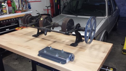
With everything laid out on the original transmission I then decided to just build a new shorter countershaft assembly as the existing one is 3 feet long!
20161002_185823%20(Small).jpg

So I have ordered some 7/8" bore pillow block bearings (these: https://www.amazon.com/gp/product/B002BBH79I/), and a 7/8" keyed shaft, 12" long from McMaster. This should allow me to build a much more compact countershaft after I remove the cone pulley from the existing transmission shaft and move it over. Then I can have the motor on its adjustable base mounted to the same plate/assembly as the countershaft which will also simplify that portion of the belt tensioning process.

Ordered a few more parts I need to complete my DC drive setup, and found a PWM DC controller that should work and be actually rated for the 1HP motor. My buddy is hopefully dropping the motor off this week, so hopefully more progress soon-ish.
 
No updates for awhile because I've been busy.

So here's where we stand:
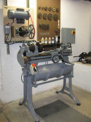
DC speed control setup has been completed, wired, and tested. I've mounted the motor and built a custom counter shaft assembly on a 24"x24" piece of 3/4" plywood. This is attached to the concrete wall via strut and is slotted for adjustment. I can therefore move it up and down on the wall to adjust the belt tension on the flat belt, and side to side to adjust for tracking/alignment.

I've got everything mounted up on the wall, and set the lathe in place.

Now I am waiting on getting the proper length flat belt.

IMG_2513%20(Small).JPG
 
Looking beautiful! I do have a question for you, though. I just picked all 12 threading change gears up for a fairly good deal, and tried setting them up just to run them (easier to oil them). Cutting a 30 TPI screw would require the 16 tooth gear on the stud, and the 60 tooth gear on the lead screw. But, when I went to set that one up for the oiling, I found the small gear on the idler would not reach the 60 tooth lead screw lathe, as the larger idler gear (they are linked together) prevented them from meshing. Have you tried it on yours? If it worked well enough, how did you do it?
 
Looking beautiful! I do have a question for you, though. I just picked all 12 threading change gears up for a fairly good deal, and tried setting them up just to run them (easier to oil them). Cutting a 30 TPI screw would require the 16 tooth gear on the stud, and the 60 tooth gear on the lead screw. But, when I went to set that one up for the oiling, I found the small gear on the idler would not reach the 60 tooth lead screw lathe, as the larger idler gear (they are linked together) prevented them from meshing. Have you tried it on yours? If it worked well enough, how did you do it?

Well that I cannot tell you. I have every change gear except the 60 tooth it appears. I haven't tried installing any other change gears yet, just inventoried.
 
Lathe is under power! Belt is way too long, need to level it out, etc but it is spinning! Cut some test chips on aluminum, still need to learn what I'm doing but it's a start!


The chuck that is on the lathe is a three jaw independent. I was having a hard time getting it indicated in. I think I will be searching for a self-centering chuck soon!
 
Back
Top