The New South Bend 10K

I am reviving this thread to get some advice on a DC motor conversion.
I am considering going with a higher RPM DC motor to get greater spindle speeds. The factory motor is a 1HP 1725 RPM AC motor. The first question is how much DC HP do I need? Should I go with 1HP or can I get away with 3/4 HP? It is my understanding that the DC motors have greater starting torque?
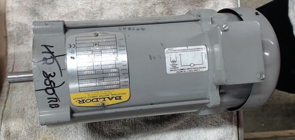
I found a nice Baldor DC 1 HP 2500 RPM motor that would probably work. There are a lot of choices if I go down to 3/4 HP. (I am not talking about treadmill motors.)
Robert
 
A real 3/4HP DC motor with a good controller will work fine but grab the 1HP Baldor if you can get it at a good price.
 
s-l1600.jpg

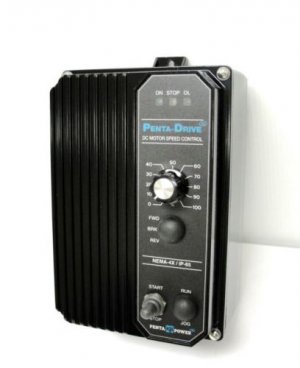
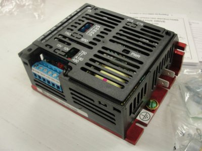
What kind of controller would you recommend? I was looking at the KBPC 240. One thing I would really like to have is dynamic braking to stop the machine quickly for safety.
s-l500.jpg

Robert
 
I can't read most of the data on the motor but it looks like a good one. It's totally enclosed which is good. I'm not familiar with that controller but the specs look good. For best performance you'll want to add a tachometer generator so that you have closed-loop control.
 
Th
I can't read most of the data on the motor but it looks like a good one. It's totally enclosed which is good. I'm not familiar with that controller but the specs look good. For best performance you'll want to add a tachometer generator so that you have closed-loop control.

Thanks for your input John. The tach sounds like it will really complicate this. I would love to have a digital speed control where I can just dial in an RPM and the controller will keep it there. Anybody have a controller in mind? I'm not sure how to hook up a tach with that KB controller and it is analog.
The seller won't move on the price of that motor so I will keep looking. I feel like the 1HP 2500 RPM will be perfect.

R
 
Well here we go on an adventure! I hope ya'll will advise me as needed with this one.
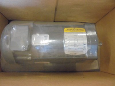
I just bought this:

s-l1600.jpg

s-l1600.jpg

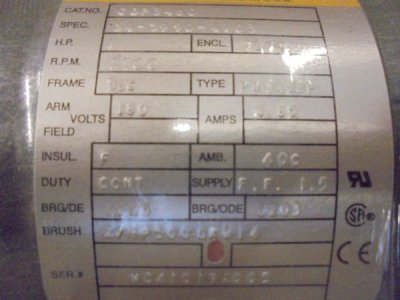
It's a TEFC 180V DC PM Baldor. The plan is DC conversion of my already overpriced South Bend!

I really want to have dynamic braking so my plan so far is to use this KB controller. It has "regenerative braking." I am thinking about keeping the existing forward-off-reverse switch and the existing emergency stop to trigger the dynamic braking (as well as the off position). I will also have a line voltage cutoff before the controller but I assume that would be a" coast to stop" if tripped. Any thoughts on this? The new motor is a 2500 rpm motor so the added speed will be nice.

s-l1600.jpg

The lathe is currently plugged into a 120v source so first I will need to rewire the shop for 240v where the lathe is. I will start on that and start to accumulate the remaining items for the conversion.
One obvious issue it the current motor is a 90L frame mount and the new one is a 56C.
I will keep you all posted on progress.

Robert
 
Problem #1.
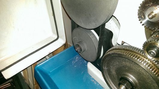
Old motor has a 19 mm shaft with a keyway. New motor has a .625 shaft.
Do I sleeve the pulley and re-bore it? Should I first machine out the ID to remove the existing keyway? (I think yes, if there is enough material) How about a flanged bushing that attaches with three screws?
Should I just make a new pulley ( not a simple task. It's a 3 groove poly V with 2 diameters)

30479655366_2098397f21_h.jpg
Please chime in!
Robert
 
Ding dong ding ding, if It were mine and I had the material , YUPP make a new one. You can have the other motor as a just in case YA Need it. Things happen and its best to be prepared. Like you said easy to make . Yours will be better I bet.
 
  • Like
Reactions: rwm
I am thinking about machining a new motor pulley from scratch rather than trying to modify the existing.
Unfortunately the motor pulley is metric and I am not sure how to go about this task. It is not like the standard J section pulleys. It is made by a company called Bando. The most detailed drawing I can find is here:
30507994222_7e9586def3_b.jpg

I have no idea what the angles are. They appear to be close to 60 deg. Has any one cut one like this?

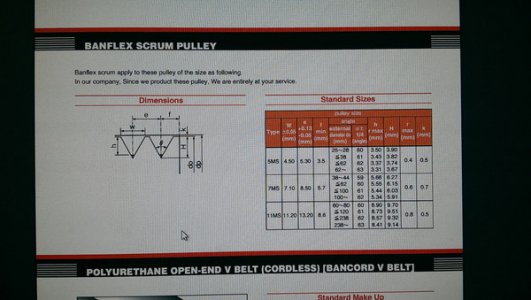
Edit: OK I found this hidden away on the internet

29996099204_482a2fe4b1_h.jpg

Apparently the pulley angle if pretty close to 60 deg. I guess I can use a thread cutting tool and make sure the groves are 5.3mm apart. Not sure yet how to gauge the width of the groove. I am thinking plunging the tool to a specific calculated depth?
R
 
Last edited:
Back
Top