
the nearest ones I see are the correct casting number, but at £180 for the half nuts and another £75 postage and import duties from the USA to the UK, thats £5 more than i paid for the lathe, I am resigned to the fact that getting parts in the UK will be pretty near impossible and shipping costs from outside the UK will be high, for that price I can print out about 50 sets of ABS half nuts, so if they last a few months per set....

-
Welcome back Guest! Did you know you can mentor other members here at H-M? If not, please check out our Relaunch of Hobby Machinist Mentoring Program!
You are using an out of date browser. It may not display this or other websites correctly.
You should upgrade or use an alternative browser.
You should upgrade or use an alternative browser.
100 year old South Bend 34 Rustoration
- Thread starter Grendel
- Start date
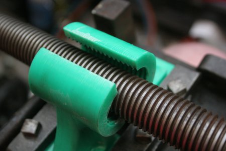
its driven by a keyway driving a worm on the leadscrew, the half nuts are only for threading, and as i dont have a threading indicator will be engaged, then left engaged while I thread, reversing the lead screw back to the start of the thread
well today I had a chance to machine the half nut dowels out of some 14mm steel bar, centre drilled, faced off and turned down to 12.6mm on my unimat with live centre support, 0.1mm cut hand fed, produced some lovely chips, the half nuts move as they should, and open and close, they also seem to grip the lead screw well, whether they work under power will be the test once I have the lathe rebuilt.


Attachments

- Joined
- Mar 5, 2012
- Messages
- 314
The half nuts look great
could you make me a set? Mine could be replaced same year and model
and year as years but not used that hard. The original owner rebuilt electrical motor. The half nuts and worm gear hav seen better days
could you make me a set? Mine could be replaced same year and model
and year as years but not used that hard. The original owner rebuilt electrical motor. The half nuts and worm gear hav seen better days


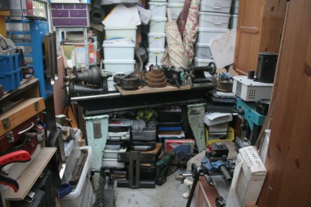
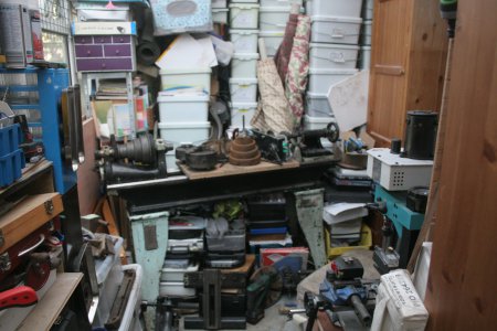
well its been a while, but other things got in the way, and some tidying needed doing to be able to progress to the next stage, anyway, this morning the tidying was completed and I had a space for the legs, after wrestling the bed next to the legs it was then a case of wrangling an engine hoist through the house and setting it up in a space no bigger than the spread of its legs, after this it was a matter of minutes to lift the bed onto the legs, aligning the bolt holes was fun, but eventually it was all completed, the headstock and tailstock were lifted up and placed on the bed, 


after this it was time to look at the bed and do some clean up work, there was a spot on the carriage ways where there was a section a foot long that was badly pitted with rist, I have worked this with a smooth file to break through the rust, then gradually finer stones have been used to smooth out the surface, the pits wont overly affect the carriage movement, but it needs to be smooth, I will work on this until I am happy with the carriage movement.


this last picture shows the state it was in before, this is right at the end of the ways, past the tailstock, so is not as crucial, but it will still be cleaned and smoothed.
next will be the headstock and tailstock ways, these have some bad damage near the chuck, but this area isnt needed as much, as neither the headstock or tailstock run in this area, it might be an issue for the steady rest though.
after this it was time to look at the bed and do some clean up work, there was a spot on the carriage ways where there was a section a foot long that was badly pitted with rist, I have worked this with a smooth file to break through the rust, then gradually finer stones have been used to smooth out the surface, the pits wont overly affect the carriage movement, but it needs to be smooth, I will work on this until I am happy with the carriage movement.
this last picture shows the state it was in before, this is right at the end of the ways, past the tailstock, so is not as crucial, but it will still be cleaned and smoothed.
next will be the headstock and tailstock ways, these have some bad damage near the chuck, but this area isnt needed as much, as neither the headstock or tailstock run in this area, it might be an issue for the steady rest though.
Attachments
so the machine is back together and it was time to deal with the broken thread on the reverse shaft, this was mashed when i hit it with a copper hammer and both split n half and mushroomed, yes I could have brazed it and retapped it, but I went a different route, i milled the thread off of the end of the shaft, chucked it up in my unimat to get a centre point on it, then drilled it out with a 8mm drill (should have been a 7.9mm, but that was the closest I had and i was tapping a deep hole) after that I tapped it out to 3/8" Whitworth (3/8 16tpi) to a depth of 30mm to take a handy socket head screw i had, this with a washer will retain the gear on the end of the reversing shaft, enabling gears to be changed out, at a later date this can be replaced with a custom stud with the correct thread on the end to take the old nut, if I want to bring it back to original, meanwhile the socket cap screw does the job
well trying to fit a 5 foot south bend into a workshop no bigger than 8 ft x 12 ft and thats no surprise, theres another lathe and a mill in there too (Unimat lathe and seig mill). Once is up and running I will clear more space around it.Looks a bit cluttered in there.