100 year old South Bend 34 Rustoration

well trying to fit a 5 foot south bend into a workshop no bigger than 8 ft x 12 ft and thats no surprise, theres another lathe and a mill in there too (Unimat lathe and seig mill). Once is up and running I will clear more space around it.
Please don't take offense, we all do the best we can with what we have.
There is a Youtube guy, Dudley Toolwright, he is very talented, his shop is so crowded you have to wonder how he does it.
He has to open his garage door to move machinery out of the way to use others.
 
I think clickspring (youtube channel name) has one of the smallest shops I've seen at 5.5 x 12.3 ft:

He does amazing home machinist work

clickspringshop1.jpgclickspringshop2.jpg
 
You have a little bit less than mine
i have a 10’ X 20’
southbend 13x5 lathe
enco 9X54 mill
15 gallon air compressor (vertical) with secondary 30 gallon tank
drill press 2, (1) post mounted (1) bench
2 grinders
1 knife sharpner
6’ long tool box with top boxes
2 stand up lockers (tool storage)
work bench 24” wide X 10’ long
and a standby generator that I have to move out before I can work
 
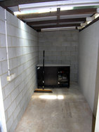
well if I extend into the second half (woodworking) of the workshop, there I have an L shaped workbench, a table saw, a bandsaw, a pillar drill, a bench drill, a planer thicknesser, 4 bench grinders (stored under the bench, one has a water wheel, one a sanding belt and 2 standard, one rigged out for polishing, add to that a 12" bench mounted 3 in 1 brake roll and shear, plus a small 1/2 ton fly press, everything in the wood shed is on wheels and gets rolled out to the middle for use (except the band saw and pillar drill, space is definately a premium, so i will have to find a new home for all the stuff boxed up behind the lathe.
thats all in a 24 foot x 8 ft space (including the metal workshop area, so 2 12x8 foot rooms, fortunately I only need to fit me in there with the tools.

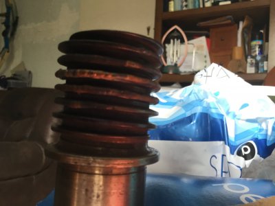
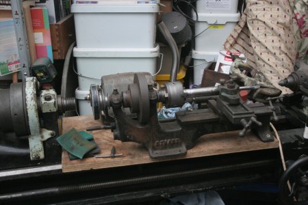
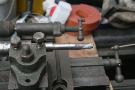
today I was trying to get the counter shaft up and running, this will be difficult as it has a slightly bent shaft from removal, none the less, a third small lathe has been sat on a board on the south bend to try and true this up, the shaft ids too long to turn, as I cant fit the tailstock on the end of the bed to support it, so I dialled in the shaft and spun it up and am using a small hand grinder to gradually true up the end of the shaft as that had also been mushroomed, once i am happy I can get a bearing over the end I may be able to use a bearing block to support the tail end.needs must at the moment until I have the big lathe running its the best option i have. once the big lathe is up and running I can turn a new shaft for the counter shaft., sort of fix A to get B running to replace A
 
You have done a lot of work on the old girl
it looks great
I just got my worm gear back from welding
next is to reground (clean up the welds) it
if I can figure out how to take pictures I will post them
 
well last night I saw a post on the south bend lathe facebook group, which was the mount for the gear cover, I have a gear cover, but dont think I have the mount for it ( actually I may have but not recognise it, but as soon a s i spotted it mounted using the spare V way at the headstock end of the lathe it got me thinking. I have been trying to think how to mount the counter shaft and motor, and was thinking I would need to drill into the bed or legs to achieve this, but the picture i saw showed me another way, by making a bracket that mounts to that spare V way, so out with fusion 360 and a few measurements taken off the lathe and I have designed a mount that will fix to that v way, the prototype is currently 3d printing in ABS, and I have made allowance for an 8mm thread in the bottom to tighten the prototype to the lathe bed, a pair of these will provide the necessary pivot point to support the countershaft and motor assembly (pics later when its finished printing.
 
heres the view of the STL file
 

Attachments

  • lathe motor support.PNG
    lathe motor support.PNG
    25.1 KB · Views: 9
well I went out for a walk, and by the time i arrived home the part had printed, I did need to run an M8 tap through to clean up the printed thread (not unusual) but when I tried it on the lathe it was a perfect fit, the 1/2" hole through will form the pivot point for the countershaft and motor unit, now to print a second, ideally i would have rounded over all the outer edges, but this was just the prototype to see if it fitted the ways, which it does perfectly.
 

Attachments

  • IMG_3700.JPG
    IMG_3700.JPG
    3.6 MB · Views: 6
  • IMG_3701.JPG
    IMG_3701.JPG
    3.1 MB · Views: 5
okay more pictures, the arrangement I am using to true up the end of the shaft, not really a problem as the bearing rides n the inner end of the shaft where its not bent, next the motor support mounted on the lathe, such a good fit, , then finally i realised what this part was, it is of course the mount for the cover, that also bolts to the lathe way down that endIMG_3706.JPG
 

Attachments

  • IMG_3704.JPG
    IMG_3704.JPG
    3.4 MB · Views: 8
  • IMG_3705.JPG
    IMG_3705.JPG
    3.2 MB · Views: 8
  • IMG_3707.JPG
    IMG_3707.JPG
    3.2 MB · Views: 7
  • IMG_3708.JPG
    IMG_3708.JPG
    3.2 MB · Views: 9
  • IMG_3709.JPG
    IMG_3709.JPG
    3.1 MB · Views: 9
Back
Top