32x40 H -- Gas Engine

B

BRIAN

Forum Guest
Register Today
I am getting the itch to build another engine, so I have done a doodle of a possible candidate.
A gas engine.

img004.jpg
32x40 mm Iron head and bore, fabricated steel crank case, 32cc, water cooled barrel, air cooled head. twin flywheels, splash lube,
Looks like it may be a possibility.
Brian.

img004.jpg
 
Re: 32x40 H

A bit more doodleing and we have the section through the head looking like it will work??

005a.jpg

Onward and upward.
Brian.

005a.jpg
 
Re: 32x40 H gass engine

That's the doodles done now to look for 60x60 iron bar.


Gas engine 32x40 H.jpg
Brian.

Gas engine 32x40 H.jpg
 
Re: 32x40 H

I'm here waiting Brian.

"Billy G"
 
Have orderd material for the barrel --head--liner and piston, now waiting on the postman. the first working drawing for the Barrel is done. This Q Cad is Good.
Brian
 
The lumps of iron have arrived, so it's time to start making CHIPS

Brian.
P1012677.JPGP1012677.JPG
OOps 2 for the price of one.

P1012677.JPG
 
Brian,
Your builds are magnificent and I am seriously looking forward to seeing this one, since I was an industrial engine tech in one or more of my past occupations. Are you planning to use a water pump or heat siphon like my small diesel tractor. It has no water pump but relies on the difference in the heat to move the hotter water to the radiator. That would save you considerable time and head aches unless you absolutely must have all the extra goodies like a pump, belt, and radiator. Please keep you progress coming!!!!

Bob
 
Hi Bob
This engine will work with a thermo siphon system but I am intending to make a plunger pump driven by a eccentric on the end of the camshaft. I will draw up both systems for the plans / instruction manual, when the time comes.
At the moment I am truing up the stock on the mill, photos to follow.
Brian.
 
Now the chips are flying.
I don't have a reliable mill vice so I am using my dividing head as a angle block to provide a vertical surface and 3-2-1 blocks to keep things square. this also helps to keep the mill head nearer the table improving the rigidity of the machine.
First job was to square up the material for the cylinder head.
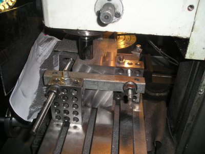

P1012684.JPG

Then mill out the lower part of the head, ready for the serious work later
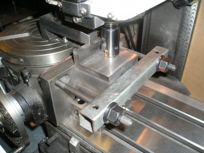
P1012686.JPG


Then I set up the material for the liner and piston in the lathe, for similar treatment. at the moment I have kept the the piston blank attached, thinking that i may use the liner material as the chucking piece.
the other option is to mount the piston blank on a spigot to do the outside, then remove the spigot, and do the inside,???
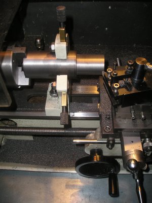
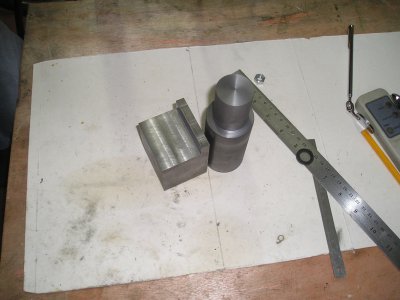
P1012690.JPG


P1012691.JPG

We have visitors arriving tomorrow so work will be on hold for a few days.
Now I have to dig out the lathe from all those chip's.

Brian.

P1012684.JPG P1012686.JPG P1012690.JPG P1012691.JPG
 
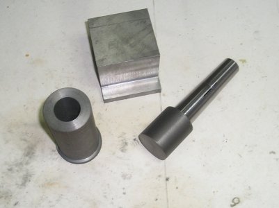
Back on the engine again, mounted the piston blank on a mandrel, and roughed out the liner.

P1012695.JPG

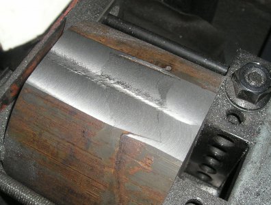
Then started work on the barrel blank and soon found that what I thought was mill scale was something more serious. It looks as though the casting process has been stopped and restarted, causing a flaw that may run right through the bar. the supplier was contacted an a new piece is in the post with profuse apologies.

P1012680a.jpg

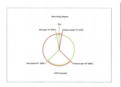
So while I wait I have done the diagram for the valve timing.

img011.jpg

Now to set about ordering the 10mm alloy plate for the crank case.

Its all go you know.

Brian.

P1012695.JPG P1012680a.jpg img011.jpg
 
Back
Top