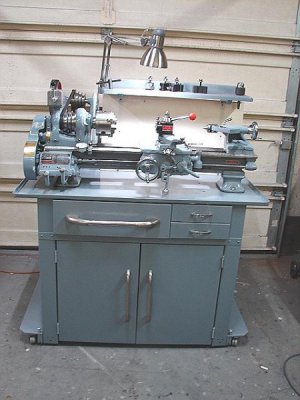
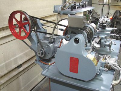
9A project completed

Very nice, thanks for the writeup so far. :encourage:

I'm watching with interest as I'm in the process of tearing down a 9a cabinet model I picked up last month. Was going to clean and repaint the cabinet, put the lathe back on it, and use it for awhile. But, as is typical in my garage it's gotten out of hand and now the lathe is in 1000 pieces, with stripping and repainting starting. :grin big:
 
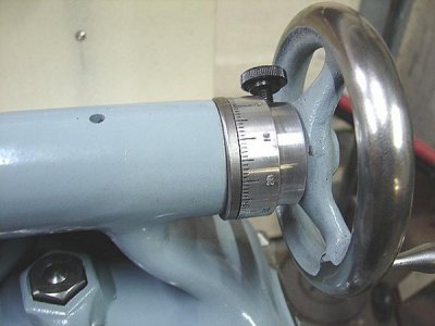
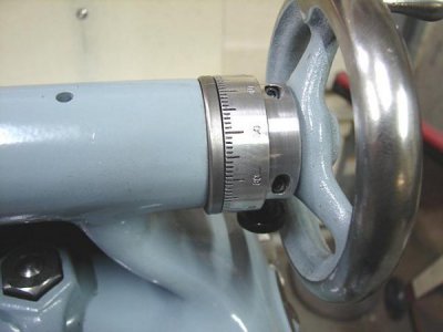
While I was assembling the tailstock, I noticed that it didn't have a graduated dial. Most lathes of that era didn't either, so I didn't think much of it. My heavy 10" has a graduated dial, but my 13" doesn't. After scouring manuals and old catalogs, I learned that the only model that came with a graduated dial on the tailstock was the 10" models. Not that it is a necessity, because the quill itself has a 1/16" scale on it, but it's nice to have definition between the lines, especially when chambering rifle barrels.
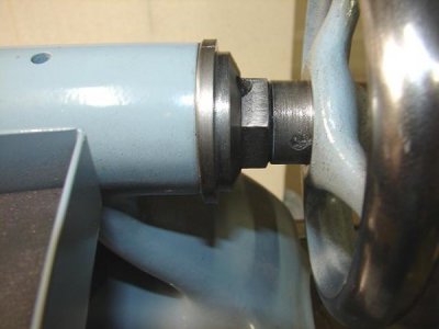
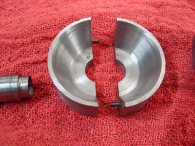
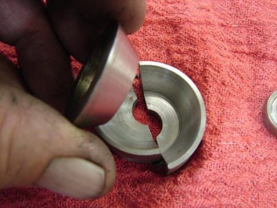
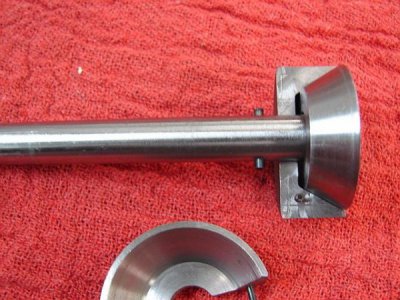
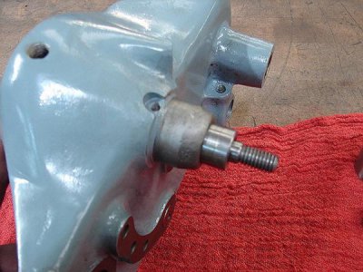
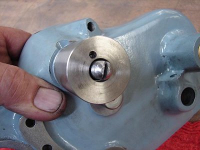
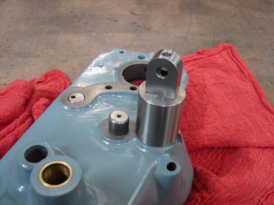
After a harder look, I figured out why there was no dial......the hand wheel is cross pinned to the quill screw with a tapered pin. There is no room to get a collar on it and get the pin in the hand wheel. The only way to make more room is to lengthen the quill screw shank to have room for a dial. That idea sounded like much more work I didn't want to do, modify the screw AND make a dial.....(I was only committed to a dial) so I had to think outside the box, so to say and came up with a better plan.
DSC02607.JPG
It was simple..................DSC02608.JPG
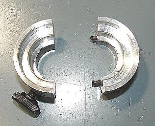
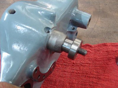
I just split the collar.DSC02601.JPG
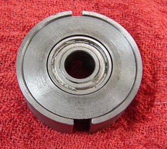
I had to turn some clearance on the retaining nut, and the collar rides on the hand wheel journal. I filed a line on the top of the nut for reference.
DSC02602.JPG
I shot that oiling hole full of grease and installed the dial, it will probably never need lubed again.
Making the dial was not hard, I used some 6061 alum. turning it oversize, then splitting with the bandsaw. I milled the mating surfaces flat, then drilled and tapped and screwed them back together. Back to the lathe to turn to final diameter and bore the through hole.
I used a spindex with a 100 hole index plate I made to index the line cuts, and the numbers were engraved with my New Hermes engraver.
The 2 halves mate together so good you can't tell where they split.
 
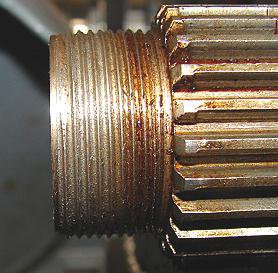
While I had the spindle out, I thought it would be nice to have a spider to attach to the outboard end. I wanted it small enough that it would clear the gear cover hole, so it could be used with the cover closed. I figured the best way was to thread the spindle.
DSC02620.JPG

I cut the threads 1-1/16"-20, mainly because I had a tap that size to use on the spider.
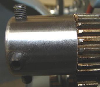
DSC02623.JPG
The threads didn't come out pretty as I wanted, but they are plenty good enough for the task. That end of the spindle has a gradual heat treat and it gets harder the closer you get to the gear.

The last major task I got into was the apron. After bath in kerosene got all the caked on crud off, I disassembled and cleaned some more. One of the most noticeable areas of wear is the slop in the carriage wheel, so I made a bushing to go into the apron casting. The shaft itself had little wear, but because of the integral gear and the handwheel is pinned to it, It didn't warrant a sleeve. Now it's not quite as tight as a new one, but quite tolerable.

Now this next step is quite a leap....and I don't know if anyone else has ever done this.
One of my pet peeves, or maybe I should say "preferences" is that I find star clutch knobs a bit out dated and cumbersome. When I got my first lathe, it was a heavy 10" with a toggle cam clutch lever. My second lathe was a 13", with a star knob clutch, that I found that was a p.i.t.a. after being accustomed to the lever on the 10". After I studied how the toggle cam clutch worked on the 10", I made a conversion for the 13".
The toggle cam clutch was available as an upgrade, available for all the SB lathes, sizes 10" and up. It was NEVER available for the 9's.

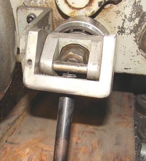
The conversion I did for the 13" is an exterior conversion. I say that because I never removed the apron to do it.
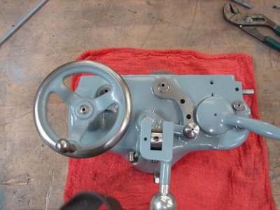
DSC02624.JPG
This consists of 2 bearings, the rear bearing is what the cam pushes against, and the smaller bearing which the yoke pulls against. The angle iron bracket keeps the whole affair from rotating. This was relatively easy on a machine of this size because the apron is larger.

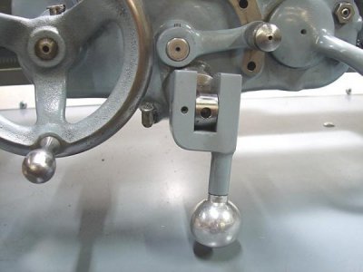
This is the toggle cam lever on the heavy 10". All of the bearings are internal.
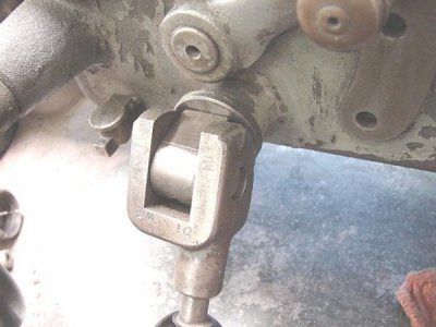
lever.jpg

The toggle cam clutch itself is different from a star knob clutch, as it has a stack of clutch discs that applies friction to the face of the worm wheel, as opposed to the inside periphery of the star knob type.
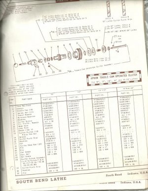
scan0001.jpg

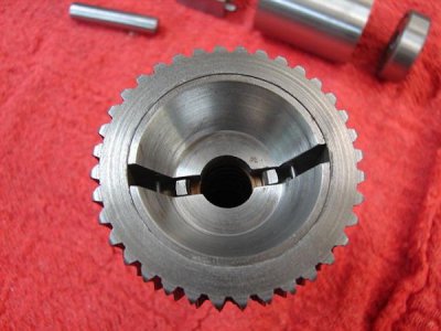
The star knob clutch uses 2 half moon wedges that expand the clutch shoes against the inside of the worm wheel when the knob is tightened.
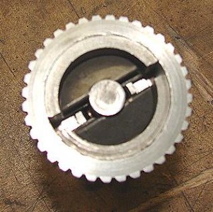
DSC02556.JPG

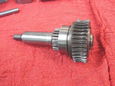
This locks the worm wheel with the clutch sleeve that is connected to the gear train. Once engaged, the whole assembly rotates as one.
The toggle cam clutch has thrust bearings on both ends, enabling the worm wheel and clutch sleeve to engage without rotating the lever. However, there is a key that retains the position of the lever assembly from rotating from static drag.

Now that is probably clear as mud, but it's easy to understand if you have the actual assemblies to study. My mission now is to figure out how to cram some bearings into the mix and make it work.
 
The original clutch was not gonna work because there was no room to get a bearing on the end and have clearance for the oil trough cover. That's where I had to do some "re-injuneerin".
The bearing I used is about 3/8" thick, so I had to make up for that amount in the thickness in the clutch. The original clutch shoes were replaced with a "coned" set I made from 12L14. Then the "expander cone" was made to contain the bearing and end up flush with the end of the worm wheel.
DSC02573.JPG
DSC02574.JPG
DSC02575.JPG
DSC02576.JPG
DSC02577.JPG
DSC02578.JPG
DSC02579.JPG

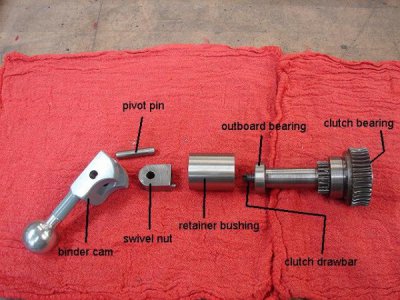
Of course I had to make a new drawbar,a swivel nut, binder cam and the retainer bushing.
The drawbar has a screwdriver slot cut in the end for adjustment once the swivel nut is on.
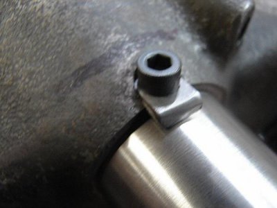
There is a grub screw in the swivel nut to lock it in place. The swivel nut has a pin that protrudes out the back that engages in a hole in the retainer bushing. That keeps the drawbar from rotating. To keep the retainer bushing from rotating, there is a clamp on the bottom of the apron.
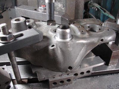
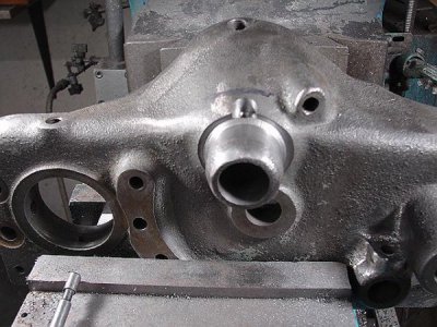
Normally on the factory version, the retainer bushing is inside the apron. The bushing has a key that mates with a keyway on the drawbar, and then the bushing is secured into the apron with a grub screw. There was not any room for a retainer bushing in the apron, so I had to place the bushing outside the apron. To make this work, the apron casting had to be modified for concentricity.
DSC02560.JPG
After the boss was milled to be square and concentric to the rest of the world, a pocket was milled for the retainer bushing clamp.
DSC02568.JPG

A hole was drilled and tapped for 10-32 clamp & screw.
DSC02571.JPG

The retainer bushing houses the outboard bearing.
DSC02580.JPG
DSC02581.JPG
DSC02582.JPG
DSC02583.JPG
DSC02584.JPG

Once assembled, the clutch was adjusted in the ball park, then fine tuned by turning the worm wheel with the retaining bushing clamp left loose. When it's good, just tighten the clamp. If further adjust is needed after the apron is installed, the grub screw on the swivel nut is loosened, and the drawbar can be adjusted with a screwdriver, but you must remove the pivot pin for access. Kinda trial and error, but doable. The angle of the lever can also be adjusted by the clamp on the bottom.

WHEWWW! That was a lot! but worth it......it works good as a factory version!
 
After I celebrated the triumph with the clutch lever, the only thing left was to paint the bed. Everything I could fit into my shop oven got powder coated, the bed and base had to be painted. I made a powder coat color sample, and took it to the local Ace Hardware for a match. After some mis-communication, I finally got the paint. I only requested a quart, for some reason they made a gallon. For the screw up, they let me have the gallon for $11.00.
Anyway, I used some gloss hardener and japan drier in this oil based enamel, and it dries in about 1 hour.
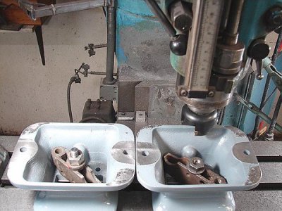
I pulled the sub bases from bed for easier handling and I noticed that bottoms of the bases were raw casting......not machined. I figured it would be beneficial that they were flat and the same height, so I gave them a clean up cut with a face mill.
DSC02595.JPG

Before final assembly, I focused on improving the base cabinet by re-vamping the drawer(s)
Originally it had one big drawer in the center that slid (and not very good) just on angle iron and flat tracks. I removed the angle iron and mounted the drawer on roller slides to the left side of the cabinet. This left room for 2 more drawers stacked on the right side. Below the drawers, I added doors to the bottom and a 12" high shelf inside.DSC02609.JPG
The hardware for the doors and the big drawer actually came from an old SS barbecue grill
that I shoulda scrapped long ago.
DSC02610.JPG
I added the shelf and backsplash for a place to store tools and way to mount the work light.
DSC02606.JPG
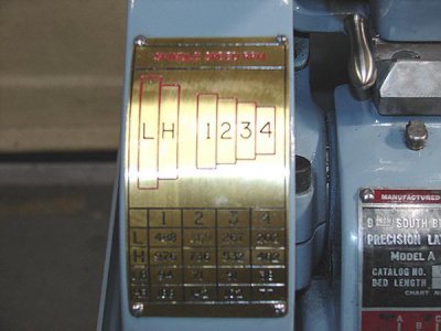
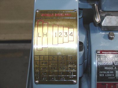
One of the last things I done....I spindle speed chart made from brass.
DSC02614.JPG
DSC02611.JPG
DSC02605.JPG
This was another fun project, that I thoroughly enjoyed and learned from, thanks for watching.
My "student" and new owner, now has about 8 hrs on this machine. I told him before he could haul it off, he had to show me some skill, so class was in session. In 4 hrs, I had him threading like a pro. A little slow, but precise. Patience is a plus...
 
That's one beautiful looking machine now, I'll say. Very nice.

-frank
 
Wow great job. My first lathe was an SB 9” with V pulleys like that. This is one of the best restorations I have seen. Congrats to the new owner!
 
What a beautiful looking lathe. The clutch conversion is a work of art. I would never have dreamed of doing it. And the cabinet conversion makes far more efficient use of the space.
Thanks for the write up.

Sent from my SM-G930T using Tapatalk
 
Repeating others, but amazing work. I wish I had half the skills and abilities you obviously do!
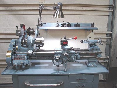
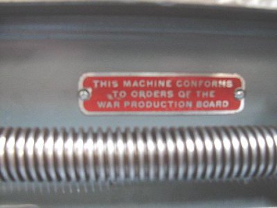
The war production board tag - how did you clean that up? I have a couple of old SB tags on my cabinet that I'd like to save, one just a little crusty and old looking, and another that someone painted partially over when they did a hurried job.
 
The biggest obstacle to overcome when restoring badges is getting them flat, second to getting them off in one piece without much damage. Once I got the war badge off, I soaked it in lacquer thinner and scrubbed with a tooth brush to strip all the paint and crud off. Once it was down to bare metal, I rolled it with a chunk of 1-1/2 round stock on my surface plate. Roll in several directions to make sure all the high and low spots become invisible.
You can use paint, or powder coat to re-color the background. Make sure the paint is applied evenly and not too thick. Once fully cured, wet sand on a flat surface like a sheet of glass or surface plate. Pay attention to when the lettering starts to appear, making sure that the colored background doesn't start to sand off where you don't want it to. If this happens,
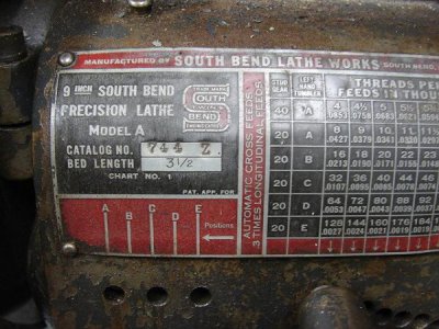
stop sanding and then use an exacto knife to scape off the paint from the lettering. This can get tedious, and you might have to use a magnifier, but depending how bad the tag is, it is the most effective way to get clean crisp letters. After the lettering is satisfactory, give it a coat of clear finish.

I didn't put that much effort into the gearbox chart, because it was still very legible and showed little wear. I scrubbed the dirt off and left the original patina or "stank" then clear coated it.
DSC02507.JPG
In the condition I got it, you can see that the chart doesn't fit very well on the gearbox casting with a lot of gaps. Typically a fit this bad usually results in several dents and dings around the edges that are unsupported. When I removed the chart, I found there was a big hump in the gearbox casting under the center of the chart, causing this not to wrap very good. I ground out the hump on the casting and then rolled and finessed the chart to fit with a slight dish in the center, making all the edges tight to the casting. I did have to move the original holes slightly to mate to the casting on account of the slight stretch. You can see part of it in this pic.
DSC02614.JPG
 
Back
Top