Acer Trump 1236 Vfd Conversion

Bamban

Active User
H-M Supporter Gold Member
Joined
Jul 13, 2014
Messages
1,051
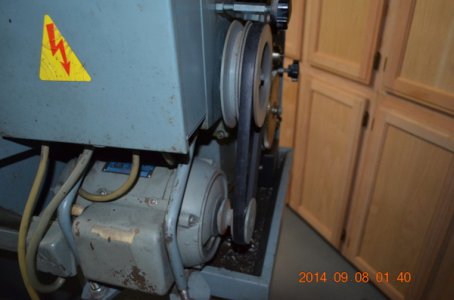
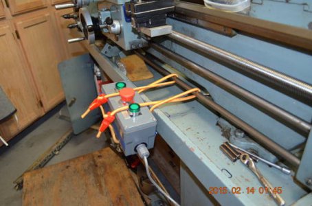
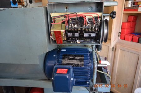
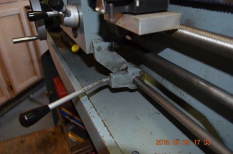
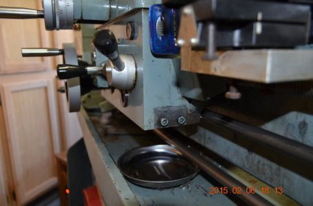
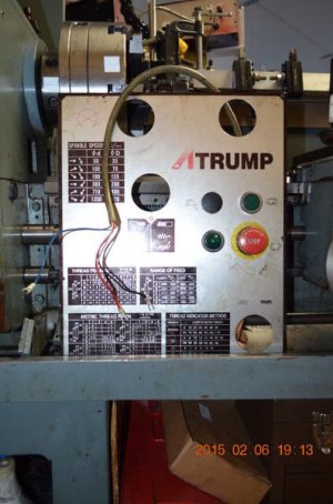
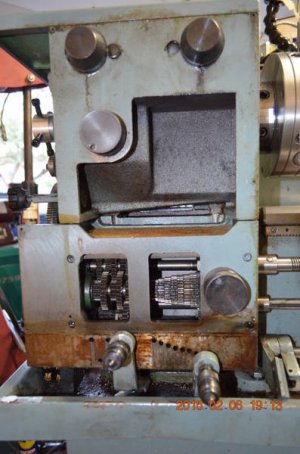
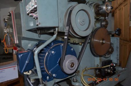
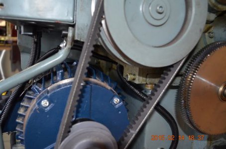
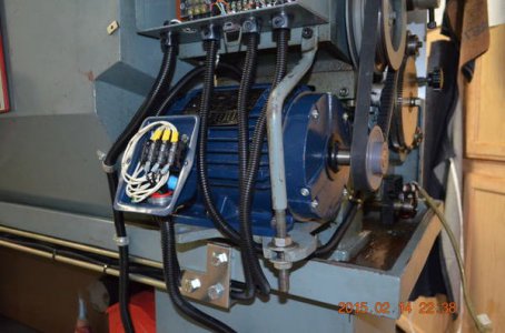
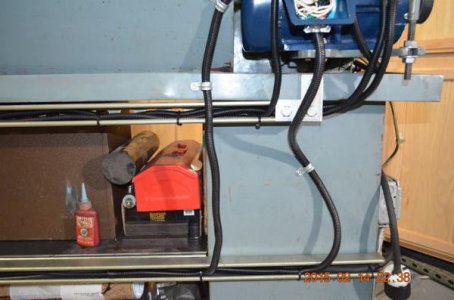
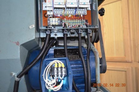
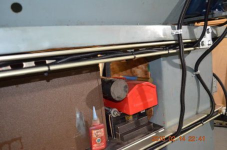
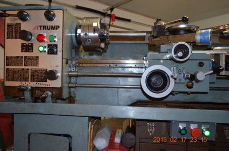
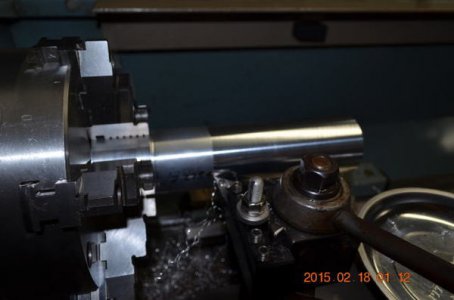
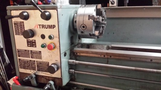
To appreciate the conversion, here is how the old set up was.
2yyqc1s.jpg
1z1hfz4.jpg

As I alluded on this thread, last entry, that the decision has been made, 3P and VFD is it. http://www.hobby-machinist.com/threads/3p-vfd-or-dc-motor.30710/ The conversion is done, done, but I will post in installment, will start with the details on what made up the conversion

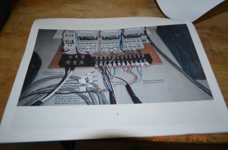
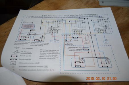
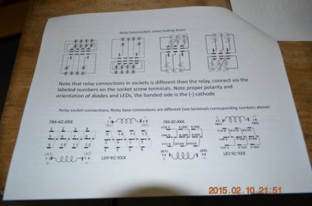
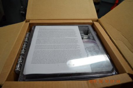
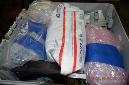
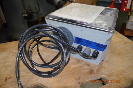
First of all this conversion is a direct credit to a forum member. His generosity and kindness, and follow through by his daily email as I went through the installation, made it all possible. I am talking about one of own, mksj. Mark not only provided the guidance, he volunteered to build the kit and all I had to do was interface the boxes, and basically just run the cables and hook up the connectors. He put together a nice 16 page manual complete with theory of operations, schematic diagram, wiring diagram, parts breakdown, and VFD configuration set up optimized for maximum performance.

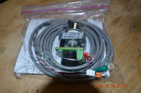
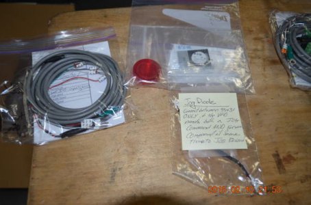
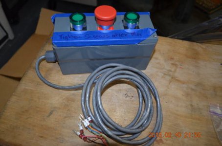
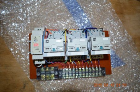
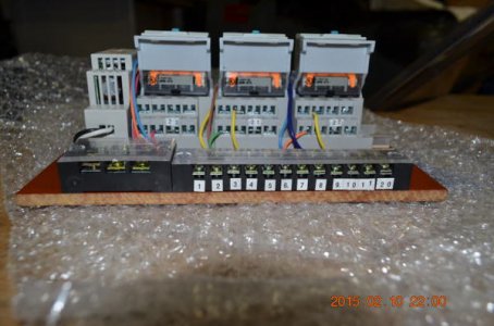
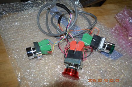
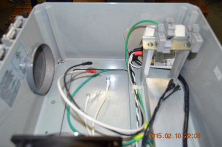
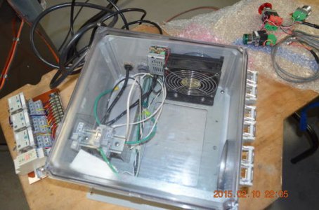
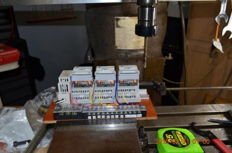
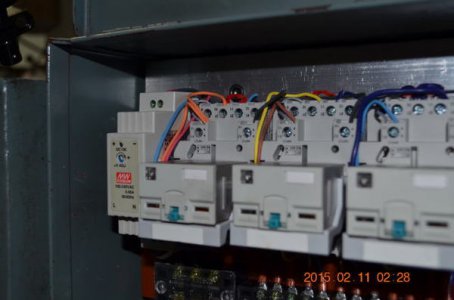
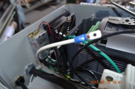
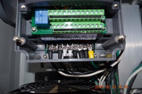
When I said he built the kit, I mean he built the entire kit, here are the pictures of the kit as it came in. I could not thank him enough for his work. Almost all the components he used are from Automation Direct, I defer to him if you folks are interested in knowing the detail components and the rationale for the selection.
xor6ae.jpg
2zqg20m.jpg
o88f0w.jpg
2cf5a15.jpg
244noy1.jpg
2uo4f9z.jpg
2z5lqag.jpg
2u7vvhw.jpg
11jn90j.jpg
1zv8l6s.jpg
dx1i5g.jpg
in4hdy.jpg
2uz8bjb.jpg
1z1b62x.jpg
28wo0ls.jpg
33bk8zo.jpg
2mxhq4i.jpg
2numyqh.jpg


More pictures tomorrow, TinyPics is acting up on me and the site limited me to 20 pictures.

Enjoy.
 
Last edited:
Mark and I exchanged a few emails discussing the lathe dimension, location of the VFD, size of the box housing the original logic control board so he can size the phenolic board properly. To allow the flexibility of the installation Mark added extra length to the wiring harness. You will see later on with the follow up pictures that his intuition is spot on. The cable lengths were just about perfect as if they were measured and fabricated on site.

Before I proceeded with the bolting down the major components I tested them for fit and best placement

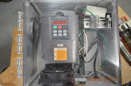
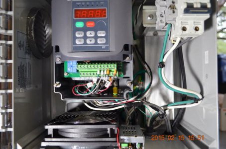
VFD inside the enclosure
2n6yj9v.jpg

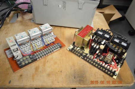
Logic control boards compared
28lgr3m.jpg

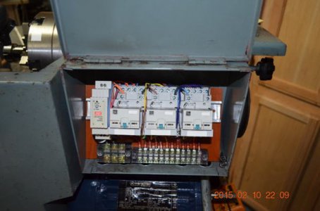
Logic control board in the box
jg72nc.jpg

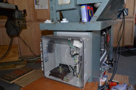
VFD enclosure resting on top of the portable heater, juts the right height to mock up the installation
alhvf5.jpg

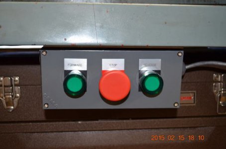
Directional control box temporarily placed to figure out the optimum location for best operator reach.
1zx5bo2.jpg


The pre-work:

Prior to getting the VFD and the control system for it, I picked up this motor on Mark's recommendation, a Marathon inverter duty motor (still not sure I understand all I read about motors) on eBay. As described in the listing 221648873231, Marathon Electric Bluechip E2207-p 2HP HIGH PERFORMANCE INVERTER DUTY Series. The original motor is smaller in size compared to this one. Originally I was afraid it would not fit. The fit is tight, but I could only use on tensioning bar and the gap between the fan shroud and the splash fan is very narrow, appears to be fine though.

14mxime.jpg


The motor directional control lever has always bugged me, due to the cramp space in my tool lay out I bumped on this thing a few times and turned on the motor. The week leading to the VFD conversion I just made it a habit to put the machine on eStop before I leave the work space. With the new directional control box for the VFD I decided to remove the manual lever and removed the 3rd rod. I kind of like the extra space to clean up under the bed.

xf9ef6.jpg
2hn0qhy.jpg


Pulled out the front panel to see what kind of space there is behind it. Looks like there is but limited.
33a6zvl.jpg
2w3x9is.jpg


The initial fit up:

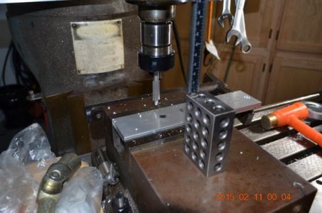
The relay logic control board though fits perfectly in the box, the old mounting holes were just free handed and not in the corners of the old board, the new one could not use the old holes. Instead of drilling new holes through the head stock I used an aluminum spacer which used the original holes, drilled and counter bored the holes, then drilled and tapped it to mount the new board.

j9loxk.jpg
35ddvl3.jpg
kevh39.jpg
9r3iop.jpg


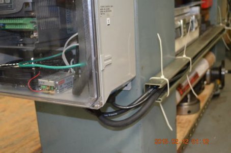
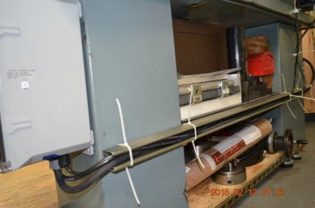
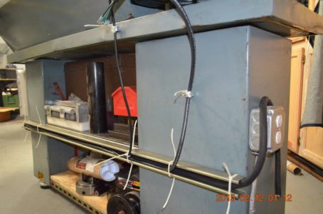
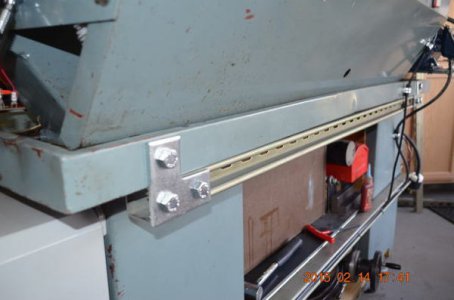
I thought hard on how to run the interconnect cables from one end to the other. Options included plastic conduit, tie wrap hangers, plastic wire molds, or use the left over Unistruts I have after I installed Unistrut based frames to connect the2 cabinets after I removed the flimsy sheet metal that previously connected them. I end up using the Unistruts.

This first one houses all the power cables, you will see later the signal cables are running on a different Unistrut. The scheme worked out nicely in the final configuration. The white tie wraps are just to temporarily hold the cables in place.

5ufhh5.jpg
33aaypw.jpg
2qlbpt3.jpg
167nmgx.jpg
2ce6pat.jpg


More to follow later, reached my picture allocation,

Enjoy
 
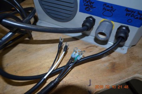
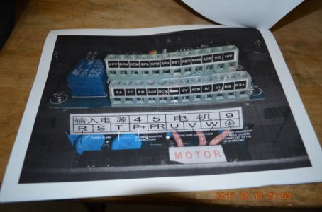
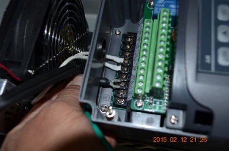
The installation did not go without any small inconvenience. When I sent the picture of the VFD input terminal strip I forgot to mention to Mark the bolt center, the spade terminals did not quite fit the slots. At first I modified a male quick disconnects connectors with hole in the middle to accommodate the hold down screws, got a couple of the spade connectors when Mark suggested just modify the spade connectors and squeeze them to fit. That saved some time

o7rdr9.jpg
30moapc.jpg
103a6me.jpg


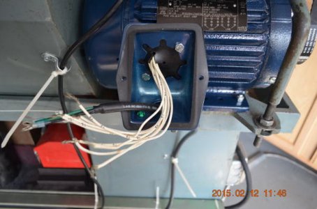
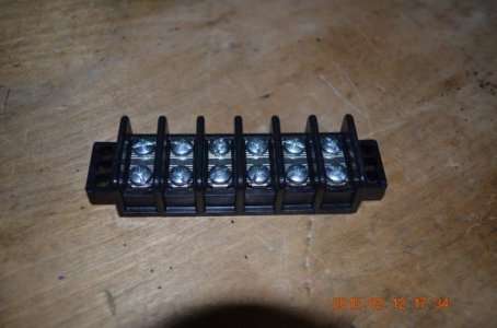
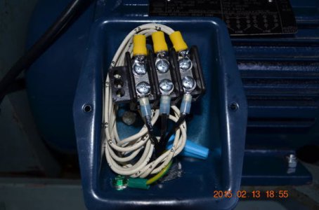
The motor did not come with studs to connect the wires and I did not want to use wire nuts so had to come up with a 3 wire terminal strip that I cut from 6 wire unit,

azf87m.jpg
2ms3l8n.jpg


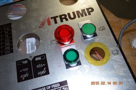
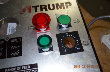
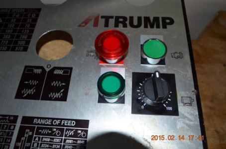
When I test fitted the front panel control, all the switches fit in the holes from the previous switches except for the new eStop, the original hole is 30MM while the new switch is 22MM. My plan was to machine adapter plates when Doctor Mark came to the rescue again. I did not know that HD sells 22MM to 30MM adapters that I just to flatten to use on the eStop hole. To cover the yellow color around the old function, I mounted the speed pot in that location.

34i4qow.jpg
1zzsxep.jpg
2pytb93.jpg
2ev6wy9.jpg


As I mentioned I would end up running another Unistrut piece to house the signal cables. I do like these grown up Leggos.

20jntd4.jpg


The Final Hook Up.

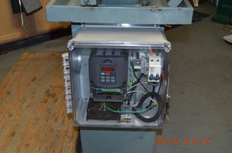
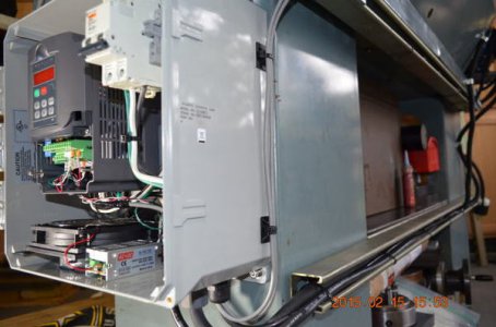
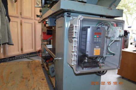
The front panel control switches wiring had to pass through the headstock, the speed control had to pass through the headstock and on towards the VFD via the Unistrut channel, the interface between the relay control logic had to go through the same channel. The directional control box wiring had to be routed around the VFD enclosure and on to the relay control logic box.

Let the pictures do the talking.

neurfs.jpg
286trir.jpg
1603f6c.jpg
2irb58l.jpg
11hfd5u.jpg
30rla4g.jpg
xdisy.jpg
2mzbfy8.jpg
2yy82n9.jpg
x39wes.jpg
 
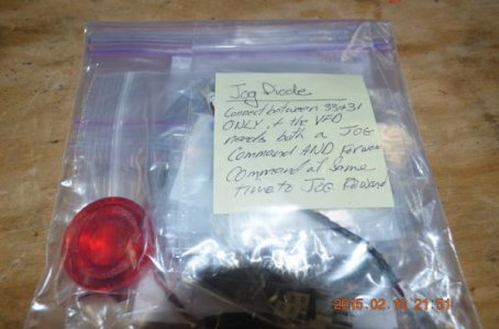
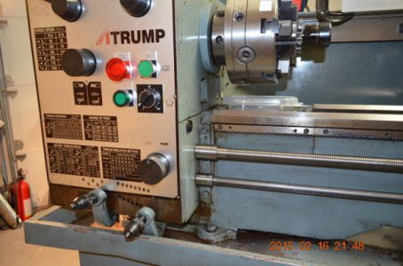
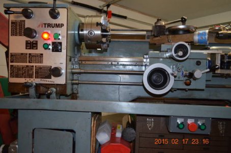
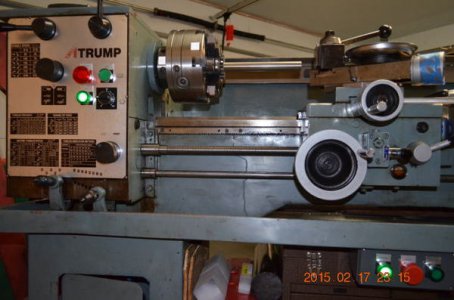
Functional testing the logic controller was the final verification to make sure I did not cross any signal wires. Prior to this test I made point to point continuity tests of the power cables just ensure I did not have any hot lines going to ground before I turned on the power. The front panel control configuration; top L is the eStop, right below it is the On switch to enable the logic controller. The top R is the Jog and below is the speed controller. Mark and I went around couple of times about the Jog button, at first when I pressed it, nothing happened. I was used to the old jog button that trips the forward contactor and was instantaneous.

During the testing we know the forward and reverse switches that activate relays and the circuits were good, so Mark suggested to swap the jog line and forward lines at the VFD. Pressed the jog switch, a momentary one, activated the spindle. The jog circuit is good. Pressed the forward switch, a latching one, nothing happened, but then a few seconds later the spindle started spinning at the low speed, which sort of reflects the programmed frequency for the jog. Turned off and repeated the test, same results. Reverted the wiring to normal and accepted the that the system will jog after a few seconds, something I can live with.

Did a clean pass on an aluminum stock I've been using to periodically test taper with

2cosck7.jpg
4vptoj.jpg
10zsqie.jpg
2m6l46r.jpg


Finally, after verifying the correct spindle rotation, I Locktited the screws holding the motor wiring connections on the terminal strip and put the cover back on. Took some videos of the spindle at different RPMs to see how the speed controller works and how stable the it is. Uncovered that the 8 inch 6J Bison set thru has too much of a mass that when spinning hard and shut it down, its momentum will keep the spindle spinning, then the VFD faults out. Another consulting email to Mark. Switched to my Bison 6 inch 3J, I can spin it at 1000 RPMs or more, the system stays happy, no faults. Looks like I may just relegate the 8 inch 6J for slow rpm work or sell it and buy a 6 inch 6J set thru, even a Gator, or trade somebody for one.

View My Video

View My Video

View My Video

View My Video


Done, done... Thank you, Mark!
 
Last edited:
Back
Top