Anti backlash mod for X2 mill

homebrewed

H-M Supporter - Gold Member
H-M Supporter Gold Member
Joined
Jul 28, 2017
Messages
2,368
I've been working on a scheme for reducing backlash on my X2 mill for some time. After some false starts I believe I've done it. It is a variation on an approach used on the Sherline CNC mills, where each table axis has two, not one, lead screw nuts. In the Sherline design (sorry, I don't have any photos) for each axis there is a second nut on the exterior of the table, and it is in close contact to the table.. Its outer diameter is knurled with a fairly coarse knurl. The nut engages a thick washer whose OD also is knurled. The washer is fixed to the table with a bolt. To adjust the backlash, the bolt is slightly loosened and the washer is rotated to turn the feed screw nut, sort of like a pair of gears. In this manner the external feed screw nut is moved in or out to adjust the backlash. Once the backlash is set, the bolt is tightened.

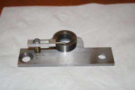
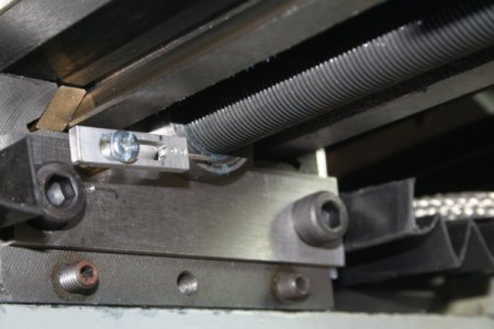
I know, verbal descriptions can be hard to unravel. But I think the attached photo will clarify things. It shows a second feed screw nut (modified from a nut I bought from LMS). The photo shows the underside of the right-hand side of the table. The nut was drilled with a 1/16" hole to accommodate a short length of piano wire that was bent at the end. The other end of the piano wire is attached to an adjuster that has a slot cut in it. To set the backlash, the screw in the slot is loosened, then the adjuster is moved to tighten/loosen the nut. BTW I also made an end plate so the external nut had a "landing pad". The stock mill table is open on both ends so it was necessary to fabricate this piece. It was made from a piece of ground steel plate. I had to D/T two holes to mount the plate on the table. It was an interesting exercise to align the hole in the plate so there was no mechanical interference with the lead screw. I made a number of prints using Inkscape, which, on my system, seems to produce pretty accurate to-scale prints. I used the prints to do some trial fitting so I could avoid any major d'oh! moments.

Unlike the Sherline approach, due to the limited range of my adjuster scheme it is necessary to do a trial fit of the the nut so you know where to drill the hole for the piano wire. But I think there should be enough adjustment range to accommodate a lot of wear. Of course, you could always drill another hole in the nut when you need to...


.IMG_5889.JPG
 
Well I may be blind or just don't understand, but I don't see a knurled nut or washer on there.
Sent from my VS987 using Tapatalk
 
I'm also a bit lost . I think a few more photos to show the set ups would be helpful. I don't get the nut and washer because there isn't any photo to show the setup and I guess I don't understand the part mounted on the end with the piano wire? To me all that does is put pressure own the lead screw making it harder to turn but how does that take out the backlash? Maybe with more info I will get a better idea of the operation and if this is something I could do to my mill also.
 
Well I may be blind or just don't understand, but I don't see a knurled nut or washer on there.
Sent from my VS987 using Tapatalk
My version doesn't use a knurl. It's got a length of piano wire, one end of which is bent to 90 degrees. That end goes into a hole I drilled in the nut. It is not glued or pinned: it is free to rotate in the hole. The slotted piece is moved back & forth, which turns the nut -- which in turn moves closer or further away from the end plate. In use, I loosen the bolt in the slotted piece, then move it to minimize backlash without making it too difficult to turn the crank handle. Then I tighten the bolt. See my reply to Chip Maker for another photo of the pieces.
 
homebrewed, I didn't get or see any other photos to see how you have this set up. Your reply does make a bit more since but still can't get how it works out to remove the backlash. Is the bracket bolt a cam that lifts to make the lead screw tighter? By the other photo all I get is that the piano wire is moving across the threads of the lead screw. I'm also not sure where the nut is and how it works if the wire is just free to move.
 
I'm also a bit lost . I think a few more photos to show the set ups would be helpful. I don't get the nut and washer because there isn't any photo to show the setup and I guess I don't understand the part mounted on the end with the piano wire? To me all that does is put pressure own the lead screw making it harder to turn but how does that take out the backlash? Maybe with more info I will get a better idea of the operation and if this is something I could do to my mill also.

Chip Maker, please see the attached photo. It shows the individual pieces: a steel backing plate, the lead screw nut, the slotted piece with the piano wire, and a standoff. The steel plate has a hole in it for the lead screw. To assemble, the handwheel/bearing assembly on the X axis is removed, the plate is slid down the lead screw and bolted into place. The external LS nut is then threaded onto the LS and run down to the plate. I found it easiest to temporarily re-attach the hand wheel and turn the LS while holding the nut.

Before drilling the 1/16" hole in the nut I ran it down the LS and marked the spot with a felt tip pin. I chose the location to maximize the amount of adjustment with wear in mind. The piano wire piece is free to rotate in the hole (it has to, in order for the design to work).

The system is similar to the split nut mod, where the nut is slotted so it can be compressed & therefore take out the slack in the nut. Another approach uses a purchased Acme anti-backlash nut, which has two nuts and a spring to apply pre-load between the two nuts and remove the slack. The split nut is a cheap way to go but you have to take the table apart to adjust it. And the commercial anti-backlash nut would likely require some serious modding to install it. My scheme just requires two drilled/tapped holes in the end of the table, to mount the steel plate; and can be adjusted without disassembling the table. To adjust, I loosen the screw holding the slotted piece then either rotate the nut by hand or push/pull the slotted piece until the backlash is minimized. Then tighten down the screw. The 10TPI thread means the adjustment can be a little fiddly but it's not too bad once you get a feel for how things work.

Some might wonder why I didn't just use a set screw to hold the nut in place. But you have to remember that the nut is threaded onto the LS. The sideways force from the set screw would increase the drag, and also push the LS sideways. Designs to avoid this seemed to introduce their own complications so I went with the scheme shown here.

BTW this mod DOES slightly reduce the range of motion on the X axis, by ~1 inch or so.

I have not done this mod to the Y axis of my mill because it's not nearly as easy to do (there is no spacing between the table and bearing block). If any of you decide to try it, you should strongly consider adding thrust bearings as well. They make a large improvement to the Y axis. If I were to do that I likely would also try to get a little more range on the Y axis.


parts.JPG
 
Correction: my mill is a true-inch machine so the lead screws are 20TPI, not 10TPI. Apologies for any confusion I may have caused.
 
OK now that I got the photo I fully understand how this works. Really a very simple fix except for the drilling and plate install. Thanks for the photo and better explanation as now I completely understand the conversion and seems it would work out on my mill as well. I will for sure look into how to make it work on my mill. Thanks !!!
 
Oh, so when you move the slotted piece back or forth, it turns the nut to take up the backlash. I see now, I think. Does it tighten or loosen against the carriage?

Sent from my VS987 using Tapatalk
 
Not the carriage per say, but the bracket you made for the carriage

Sent from my VS987 using Tapatalk
 
Back
Top