-
Welcome back Guest! Did you know you can mentor other members here at H-M? If not, please check out our Relaunch of Hobby Machinist Mentoring Program!
You are using an out of date browser. It may not display this or other websites correctly.
You should upgrade or use an alternative browser.
You should upgrade or use an alternative browser.
Greg's Logan 820 Restoration
- Thread starter gjmontll
- Start date
Re: Greg's Logan 820 Restoration - QCGB reassembly - part 1
I started overhaul of the quick change gear box (QCGB) about ten weeks ago. Finally, today, it's back together, looking nice and running good. You can go back and read the epic tale in the prior postings. Today I will show the reassembly of the repaired/replaced and cleaned up parts.
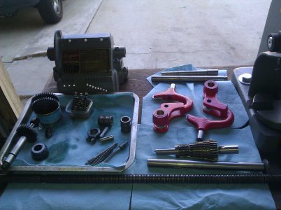
First, the table full of qcgb parts. In the center rear are the two old shafts that I made replacements for. But the old shafts will be useful for reassembly alignment tools.
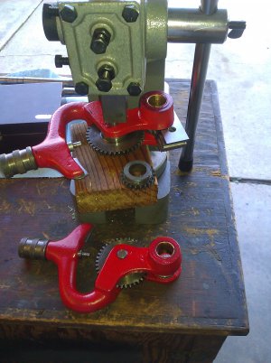
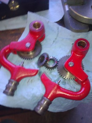
Now that the shift arms are repaired with steel repair sleeves and Oilite bushings, put them back together. The spring-loaded pin and knob assembly must go first, before the big gear. (Guess how I know this.) Then press the gear pins back in. The stack of parallels will keep the gap from closing down. (Again, learned this the hard way too.)
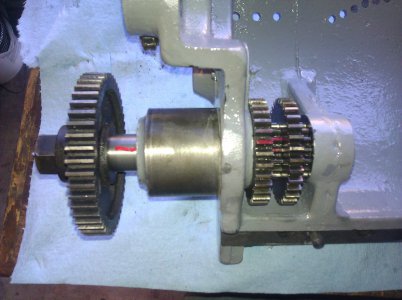
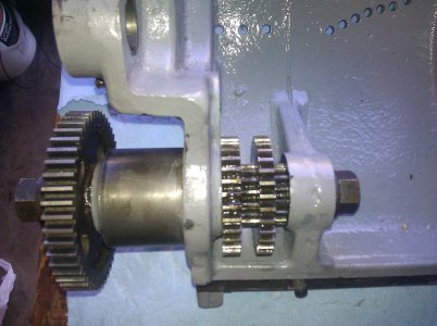
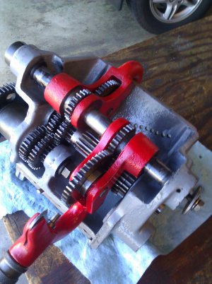
First into the casting is the input shaft and its three gears. The red marks identify the keyslots and keys on the gears and shafts. This makes it a lot easier. Having the gear on the end gives a handle and leverage. But that gear will need to come of when replacing the gearbox and putting on the drive train.
In the next posting (in a few hours), I will finish the reassembly.
Greg


I started overhaul of the quick change gear box (QCGB) about ten weeks ago. Finally, today, it's back together, looking nice and running good. You can go back and read the epic tale in the prior postings. Today I will show the reassembly of the repaired/replaced and cleaned up parts.
First, the table full of qcgb parts. In the center rear are the two old shafts that I made replacements for. But the old shafts will be useful for reassembly alignment tools.

Now that the shift arms are repaired with steel repair sleeves and Oilite bushings, put them back together. The spring-loaded pin and knob assembly must go first, before the big gear. (Guess how I know this.) Then press the gear pins back in. The stack of parallels will keep the gap from closing down. (Again, learned this the hard way too.)


First into the casting is the input shaft and its three gears. The red marks identify the keyslots and keys on the gears and shafts. This makes it a lot easier. Having the gear on the end gives a handle and leverage. But that gear will need to come of when replacing the gearbox and putting on the drive train.


In the next posting (in a few hours), I will finish the reassembly.
Greg


Re: Greg's Logan 820 Restoration - QCGB final reassembly - part 2 of 2
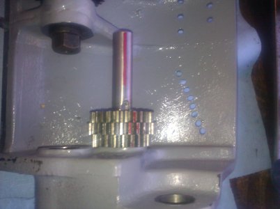
And continuing the reassembly, next comes the main shaft, the one with the dozen gears. Here's where you really need the red alignment marks. In the second picture, the old shaft is inserted from the left, as an alignment aid.
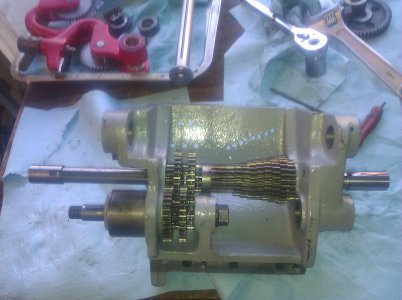
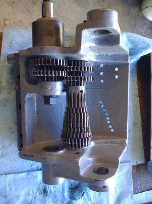
Now the slider shaft and the shift arms. They go on rather easily, but still, the alignment marks do help. And this time, I do have the gears in correctly, so that the two arms/gears are mirror images of each other. I tested each of the shift arm positions, turning the gears by hand. All turn okay, a bit stiff with the brand new bushings. Note: I did soak all the bushings overnight in oil before the reassembly. I don't know if they need it or if they are factory-impregnated. I don't know if it helped, but it couldn't have hurt.
The nameplate/threads and feeds table was cleaned up by re-doing the red and black sections, then lightly scraping and sanding to clear off the raised brass characters.
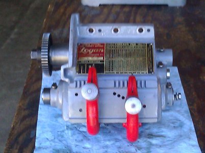
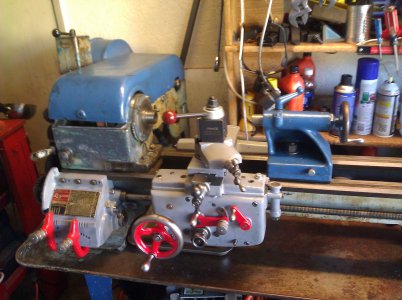
Then, inserted the lead screw and reinstalled on the lathe... Hooked up the gear train, turned it over by hand, then with power.
All works fine and sounds smooth! Ready for another 70 years? I am happy )
)
So what's next in the restoration?
Then, probably in January, the big pieces. I suppose that my lathe will be out of service for a few months as I tackle the remainder.
Hopefully I will not discover the need for the lathe to make repair parts when I have it totally broken down. If anything is going to need some parts, I'd suspect it would be in the counter-shaft area. I will check that out first with some "exploratory surgery"
Happy Thanksgiving, Y'all,
Greg


And continuing the reassembly, next comes the main shaft, the one with the dozen gears. Here's where you really need the red alignment marks. In the second picture, the old shaft is inserted from the left, as an alignment aid.


Now the slider shaft and the shift arms. They go on rather easily, but still, the alignment marks do help. And this time, I do have the gears in correctly, so that the two arms/gears are mirror images of each other. I tested each of the shift arm positions, turning the gears by hand. All turn okay, a bit stiff with the brand new bushings. Note: I did soak all the bushings overnight in oil before the reassembly. I don't know if they need it or if they are factory-impregnated. I don't know if it helped, but it couldn't have hurt.

The nameplate/threads and feeds table was cleaned up by re-doing the red and black sections, then lightly scraping and sanding to clear off the raised brass characters.

Then, inserted the lead screw and reinstalled on the lathe... Hooked up the gear train, turned it over by hand, then with power.
All works fine and sounds smooth! Ready for another 70 years? I am happy

So what's next in the restoration?
- Test/measure the headstock and tail-stock alignment (I never leveled/aligned the lathe when I moved it into my shop.)
- Overhaul the tail-stock. Hopefully, this is just a cleanup and repainting
- Fabricate a set of adjustable leveling legs, using the hockey puck idea suggested by Steve back in July
- Repaint some of the other easily removable panels, such as the gear cover and the belt cover.
Then, probably in January, the big pieces. I suppose that my lathe will be out of service for a few months as I tackle the remainder.
- Counter-shaft/motor/peg leg (clean, inspect, repaint, rewire?)
- Headstock and gear train (clean, inspect, repaint, make a back-gear knob latch mechanism)
- Bed (repaint)
- Chip tray and legs (repaint, add the leveler feet)
Hopefully I will not discover the need for the lathe to make repair parts when I have it totally broken down. If anything is going to need some parts, I'd suspect it would be in the counter-shaft area. I will check that out first with some "exploratory surgery"
Happy Thanksgiving, Y'all,
Greg


- Joined
- Jul 27, 2013
- Messages
- 295
Excellent;
Drawing motivation...
Drawing motivation...
Excellent;
Drawing motivation...
Yep, I think I need another Logan project. A friend of mine has been telling me about his old Logan that he dismantled and stored in the back of an old pick up truck that's now buried in a storage shed. He's been telling me he's going to give me that lathe for about 3 years now. Maybe it's time to motivate him to dig it out. Greg, you're probably right about the countershaft. It's probably worn where the bushings ride on the shaft. It's one of those areas that always seemed to be neglected. While you have the spindle out it would be a good time to install an endless belt also. With that and all the other work you're doing to it, it should be a smooth running machine.
Chuck
- Joined
- Jul 27, 2013
- Messages
- 295
Right on, Chuck;
See my thread for primary drive issues, as I'm right in the middle of refurbing that assembly. Just did new shaft and bushings. Yours will be slightly different, but the gist of it is the same. I am seeing that these were indeed often overlooked "way back there."
See my thread for primary drive issues, as I'm right in the middle of refurbing that assembly. Just did new shaft and bushings. Yours will be slightly different, but the gist of it is the same. I am seeing that these were indeed often overlooked "way back there."
Yep, two things that I have always found to be true with the old Logans I've had. One: The counter shaft will be worn from lack of lube. Two: You don't have to worry about spilling any dirty oil when you take the apron apart. What's left of it can be scraped off the bottom of the case with a putty knife. But I still love the machines. With a little tlc they can do a lot of good work.
Chuck
Chuck
Re: Greg's Logan 820 Restoration - Tailstock restoration, part 1 of 1
Thanks for the encouragement, y'all
This time, the target was the tailstock (t/s). In retrospect, the t/s might have been a better starting place in the restoration process, due to its relative simplicity. However, it was fully functional and had at least been repainted (blue), so the worn and ugly apron/saddle and QCGB took precedence.
Two odd things about my t/s collection of parts:
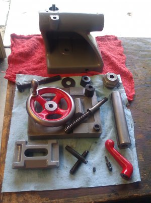
Here are all the pieces, ready for reassembly. In the center foreground are the "new" setscrews. Just to their right, the little black piece is that non-oiler plug mentioned above.
Reassembly was easy, here it is back on the ways.
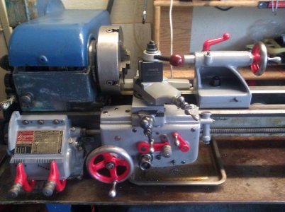
Next step will be making the adjustable hockey puck legs. I will probably drill and tap the ends of the legs for 9/16" or 5/8" leveler bolts. This is so I can get the lathe level, then I can do an alignment check (Rollie's Dad's Method?) as a benchmark before I remove the headstock for overhaul.
Greg


Thanks for the encouragement, y'all
This time, the target was the tailstock (t/s). In retrospect, the t/s might have been a better starting place in the restoration process, due to its relative simplicity. However, it was fully functional and had at least been repainted (blue), so the worn and ugly apron/saddle and QCGB took precedence.
Two odd things about my t/s collection of parts:
- the parts catalog shows there to be two oiling points on the top, both have the same part number. Mine has the one at the right end, but the one on the left was not there, instead a small, solid steel knurled plug had been installed. Interestingly, the diameter of this plug is only .19", while the "Gits-type oiler" is about .29. Until I can get a replacement oiler, I may just leave the open hole as an oiling point, then I'll have to redrill for the proper size.
- The two lateral adjustment setscrews had apparently gotten lost and replaced by hex head bolts. I turned them into the proper setscrews, turning off the hex head, chamfering the contact point, and screwdriver slotting them.
Here are all the pieces, ready for reassembly. In the center foreground are the "new" setscrews. Just to their right, the little black piece is that non-oiler plug mentioned above.

Reassembly was easy, here it is back on the ways.

Next step will be making the adjustable hockey puck legs. I will probably drill and tap the ends of the legs for 9/16" or 5/8" leveler bolts. This is so I can get the lathe level, then I can do an alignment check (Rollie's Dad's Method?) as a benchmark before I remove the headstock for overhaul.
Greg


Re: Greg's Logan 820 Restoration: Hockey Puck Leveiing Feet
Back in July, when I first started this thread and mentioned the plan to get/make some leveling feet, Steve suggested hockey pucks as the basis [unavoidable pun] for them. Steve, thanks for the great idea. I did some searching, and used ideas from yours and some folks' implementations. Here's what I came up with:
View attachment 66031
Given that the mounting holes in the bottom of the legs are almost right, I selected 5/8" -11 UNC as my thread. I may need to ream them just a bit. Perhaps it would have been better to go for 5/8-18 UNF (stronger and more mechanical advantage), but the tap and die with the coarse thread were locally available for the new tap (and die) needed for the job. Every hardware store sells the 5/8-11 nuts and bolts, I would have had to go to the local screw store for the UNFs.
I considered taking the legs to a welding shop and having nuts welded onto cast iron feet. Nah, I like doing things myself. That's why we're in this hobby, right?
Annotated Bill of Materials (for each foot)
I made five units, but whether I put one on the pegleg is TBD. I know I don't really need it, but it may be a nice convenience. For example, I had wondered why my belt cover would not come all the way down and had thought it was the adjusting screw was not right. Messing with that setting didn't fix the gap between the lid and the headstock, I now see that the countershaft assembly has been too low and that I should have raised it on the pegleg. Because the back of my lathe is up against some shelves, access to the pegleg adjustment is very difficult, and adjusting it would be a two-man job. So, I do hope I can use the 5th puck to assist (and make it a one-man job.)
Besides providing the ability to precisely level the lathe on a non-level garage floor, these feet will raise lathe somewhere in the range of 1 5/8" to 3 3/4". I am 5'8", an extra two inches or so will bring the carriage handwheel and cross feed crank up to more comfortable heights. BTW, I made these feet concurrently with stripping and repainting the left side gear cover door, so that's now out of the way.
Greg
Back in July, when I first started this thread and mentioned the plan to get/make some leveling feet, Steve suggested hockey pucks as the basis [unavoidable pun] for them. Steve, thanks for the great idea. I did some searching, and used ideas from yours and some folks' implementations. Here's what I came up with:
View attachment 66031
Given that the mounting holes in the bottom of the legs are almost right, I selected 5/8" -11 UNC as my thread. I may need to ream them just a bit. Perhaps it would have been better to go for 5/8-18 UNF (stronger and more mechanical advantage), but the tap and die with the coarse thread were locally available for the new tap (and die) needed for the job. Every hardware store sells the 5/8-11 nuts and bolts, I would have had to go to the local screw store for the UNFs.
I considered taking the legs to a welding shop and having nuts welded onto cast iron feet. Nah, I like doing things myself. That's why we're in this hobby, right?
Annotated Bill of Materials (for each foot)
(1) used hockey puck (eBay)
(1) 5/8-11 x 4" bolt
(2) 5/8/11 nut (The second will be used as a lock nut.)
(1) 5/8" fender washer (1 5/8" OD)
(1) 3/16 x 1" roll pin (It pins the nut to the bolt, so I can use a wrench to adjust/jack the leg.)
(1) 5/8-11 x 4" bolt
(2) 5/8/11 nut (The second will be used as a lock nut.)
(1) 5/8" fender washer (1 5/8" OD)
(1) 3/16 x 1" roll pin (It pins the nut to the bolt, so I can use a wrench to adjust/jack the leg.)
I made five units, but whether I put one on the pegleg is TBD. I know I don't really need it, but it may be a nice convenience. For example, I had wondered why my belt cover would not come all the way down and had thought it was the adjusting screw was not right. Messing with that setting didn't fix the gap between the lid and the headstock, I now see that the countershaft assembly has been too low and that I should have raised it on the pegleg. Because the back of my lathe is up against some shelves, access to the pegleg adjustment is very difficult, and adjusting it would be a two-man job. So, I do hope I can use the 5th puck to assist (and make it a one-man job.)
Besides providing the ability to precisely level the lathe on a non-level garage floor, these feet will raise lathe somewhere in the range of 1 5/8" to 3 3/4". I am 5'8", an extra two inches or so will bring the carriage handwheel and cross feed crank up to more comfortable heights. BTW, I made these feet concurrently with stripping and repainting the left side gear cover door, so that's now out of the way.
Greg

