Jane's Clock.

B

BRIAN

Forum Guest
Register Today
Well it started with a call from my step daughter saying they will be ariving in 4 weeks for a holiday.
It just got me to thinking that it would be nice to give them a clock to take home.
So what clock ??? After making the Brass alarm most visitors to the house are facinated by the Foliot swinging on the top so that is a good start. the alarm is not very useful, but a one strike on the hour is nice to have, and simple to do,it must be simple to make as i have only 4 weeks and a lot of other things to do.
So i am throwing traditional ideas out. this clock will be made, On the fly! KISS and ASAP are the key words.

So yesterday afternoon I made a few basic notes to get the layout of the gears. and ended up with a clock that will tick 33.7 times a minute.
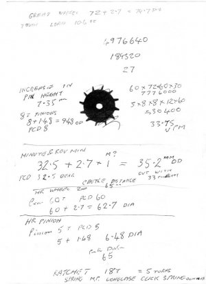
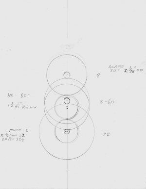
img133.jpg

img134.jpg

This afternoon its into the shop to start making chips.

I started on the escapement because I wanted to try a different method of making this component.

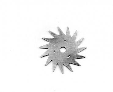
this scape has 2 wheels so the blanks where cut together.

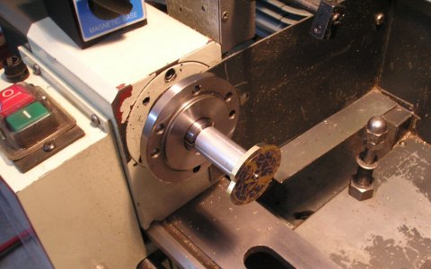
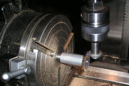
To start with 15 radial cuts where made 3/8'' deep.

then the cutter was raised until its lower edge was just level with the top of the cut one slot up.

The cutter was then raised a further .020'' to give a flat top to the teeth.

Then the cutter was fed in until the to cuts met.
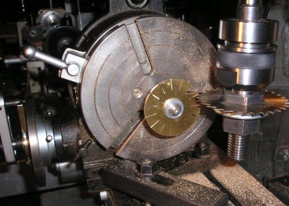
P1011629.JPG

With the unused slides locked the remainind teeth were formed.
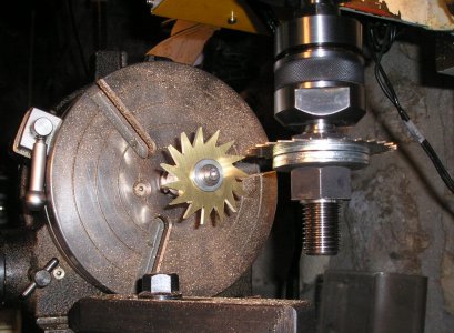
P1011630.JPG

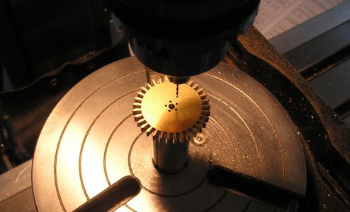
The dividing head was then moved onto its back to drill the fixing holes .
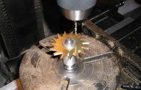
P1011631.JPG

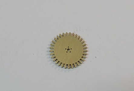
As the slitting saw was set up The faces of the ratchet teeth where cut also.
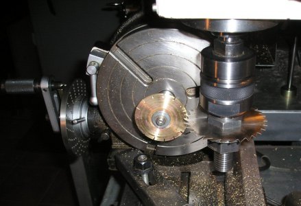
P1011627.JPG

The back of the teeth will be formed by hand.
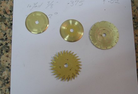

P1011634.JPG

To finish the day I made 2 flanges for the winding system.


Well thats it started Brian.

img133.jpg img134.jpg P1011629.JPG P1011630.JPG P1011631.JPG P1011627.JPG P1011634.JPG
 
Brian,

This sounds like an interesting project. There's nothing like striking out on your own and creating everything from scratch. It's a lot more rewarding than following drawings and adhering to a design created by someone else. I just bought Stan Bray's book "Making Clocks" and that's the approach he takes. He covers the theory behind clock design and clock making but doesn't supply any drawings. I'm already considering a redesign of the John Wilding English Regulator I was planning to make to add chimes. All I need to do is figure out where to get the time to finish my current project so I can get started.

Tom
 
I'll certainly be watching in awe as this comes together. :worship:

Thanks,

-Ron
 
Ok lets continue with the scape, I had drilled 3 holes to attach the 2 scape wheels to the centre boss, but the wheels need to be out of phase by half a tooth, so I moved the dividing head on 12°
and drilled 3 more holes. OK I end up with a few spare holes but I know that the assembly will be true.

img135.jpg

Now we continue with the main wheel.

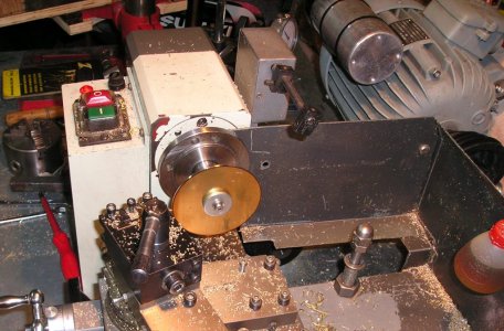
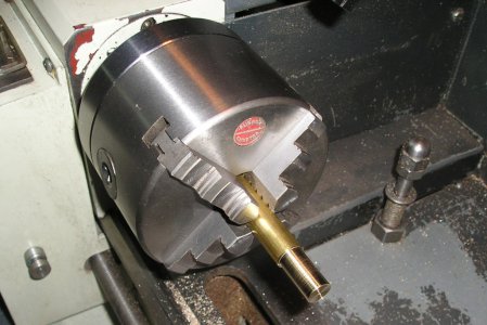
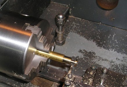
The blank was fitted to a mandrel and turned to size.

P1011617.JPG

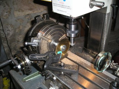
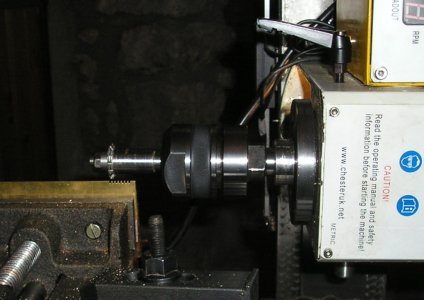
Then the mandrel was transferred to the mill for cutting the teeth.

P1011618.JPG

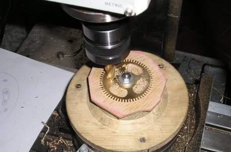
And finally crossed out with a 12mm end mill.

P1011619.JPG

That's it, 3 days down and counting. Brian.
img135.jpg P1011617.JPG P1011618.JPG P1011619.JPG
 
Very nice work Brian. Can you tell me what kind of escapement this is?
 
Hi DMS.

The escapement is a "Strob" originaly used in the St. Alban's Clock. By Ritchard of Wallingford.

The foliot oscillating bar was used in the 16 century.

The star wheel is my attempt at making the constuction simple. I may make other mods as I go along to simplfy things.

All this will probably make a good clockmakers hair stand on end. but I am doing it for fun with the hope of having a clock to give to my stepdaughter.

Wish me luck Brian.
 
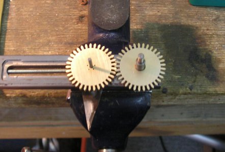
To drive the hands a clock has 2 pairs of gears a 12:1 set for the HR hand and a 1:1 set for the minutes,
These gears share the same centres, so the sum of the teeth must be the same for each pair.
On the brass alarm the drive pinion had 4 pins (teeth) this I did not like! so I uprated it to 5.

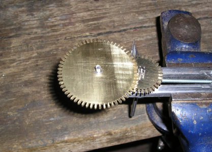
This meant it now had to have a HR wheel of 60 teeth; add the pinion 5 to get the sum, 65 ok.
Now if we halve this we get the number of teeth for the minute wheels. 32-1/2 teeth ,Oh Dear!!!

So we have to fudge it, we make the blank for 32-1/2 teeth but cut them with 33.
This is common in clocks.

First cut the blank to size, this gear has a very small centre hole with a 6 BA screw.
So it is locktited to its mandrel face.

P1011617k.JPG

Cut the gear with 33 teeth.

P1011618k.JPG

Lay the dividing head down, centre it under the drill, move off half PCD, then drill the 5 holes for the pinion pins.

P1011620o.JPG

Nearly finished gear.

P1011622.JPG

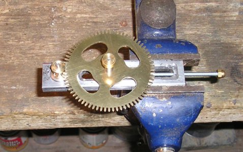
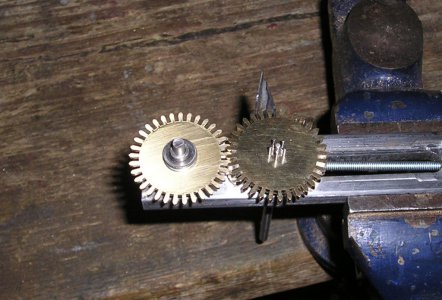
Make the other one and test the meshing.

P1011624.JPG

And that was it for today. Brian.

P1011617k.JPG P1011618k.JPG P1011620o.JPG P1011622.JPG P1011624.JPG
 
Last edited by a moderator:
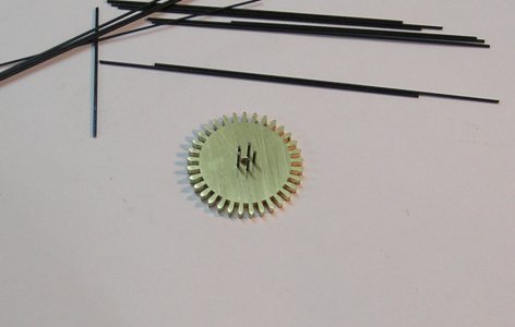
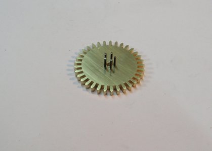
The next stage was to hammer in 5 short lengths of pinion steel
, trim, and grind to length.

P1011629a.JPG

P1011631a.JPG

P1011632.JPG

The pinion blanks are prepaired by turning to size and keeping a small pip in the center this is used to find center when moving out to the PCD.

P1011636.JPG

Then turn the bobbin , deep enough to clear the teeth of the gear but remembering that the center hole still has to be drilled.

P1011637.JPG

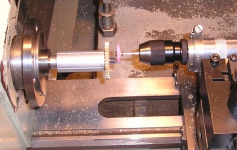
The lathe is then set up for indexing, and the tool post drill fitted. after drilling the holes, fit the pins, grind flat, drill the hole for the arbor, then part off.

P1011638.JPG

Pinion on test.

P1011639.JPG

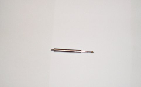
The main arbor was made from a length of 1/4" silver steel with 2 short lenghs of 1/8" ss inserted into the ends then finish turned.

P1011646.JPG

And so on we go Brian.

P1011629a.JPG P1011631a.JPG P1011632.JPG P1011636.JPG P1011637.JPG P1011638.JPG P1011639.JPG P1011646.JPG
 
If things look out of order its because I have been waiting for brass to arive.

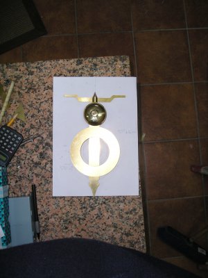
So the next thing was to cut the notches on the Foliot ,for this I used a pinion cutter that gives a nice V notch when used in Rack mode.

P1011647.JPG

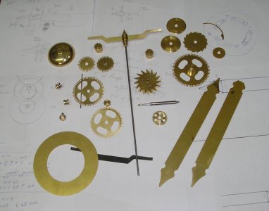
This gave me the basic parts to see what it will look like.

P1011649.JPG

After cuttin a few more gears I now had the ones to see if the "fudging" of the numbers worked

First the Min wheels are set up.

P1011659.JPG

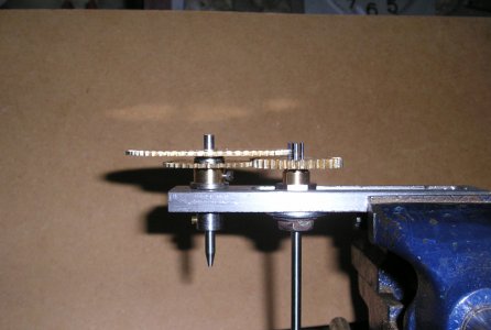
Thn the Hr wheel is stacked on top .

P1011660.JPG


Side view All is ok.

P1011661.JPG

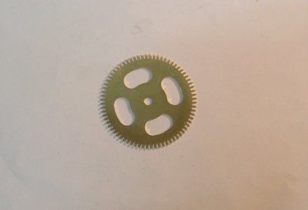
Back to the mill for crossing out.

P1011663.JPG

Getting quite a pile of parts now.

P1011664.JPG


Getting on, but so is the time??


Brian.

P1011647.JPG P1011649.JPG P1011659.JPG P1011660.JPG P1011661.JPG P1011663.JPG P1011664.JPG
 
Brian,
Just great that you can design a clock on scraps of paper quite awsome.I like the photos posted of various machining steps.
Will be quite a unique gift hand crafted one off original.
Ian.
 
Back
Top