- Joined
- Oct 16, 2017
- Messages
- 5
Sorry for the delay I just found out about the bell at the top of the forum. The levelling feet are those:What size leveling feet did you use
LPST-1.88-1/2X13-4.00-C1 (8T4LIT)
From JWWinco.
Sorry for the delay I just found out about the bell at the top of the forum. The levelling feet are those:What size leveling feet did you use
Thanks those are the same ones I ordered starting the stand build todaySorry for the delay I just found out about the bell at the top of the forum. The levelling feet are those:
LPST-1.88-1/2X13-4.00-C1 (8T4LIT)
From JWWinco.


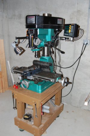
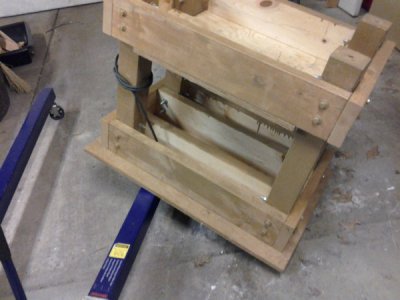
What gauge sheet metal did you use for your drawers ???I purchased this mill-drill used and the original stand came all warped and busted so I built this one. The original was 18wx26dx24h, this one is 28wx31dx29h. Used 1-1/4 steel tube 1/4 wall all around and made drawers (24x30x4) to hold all the stuff. This stand weighs about 350 pounds (plus about 350 pounds of tooling ), it dampens vibrations a lot compared to the factory one.
I actually regret not making two columns of drawers. There would have been enough room underneath the chip tray, you can never have too much storage!!
I really appreciate the adjustable feet, it allows me to put the mill level on my slanted garage floor.
I made the chiptray almost twice as wide as the factory one and it could be wider, I still get many chips on the ground.
I used enamel paint, some cutting fluids have bubbled it so if I was to repaint it, I would look for tougher paint...
View attachment 247635View attachment 247636
Sorry about the bad pics.
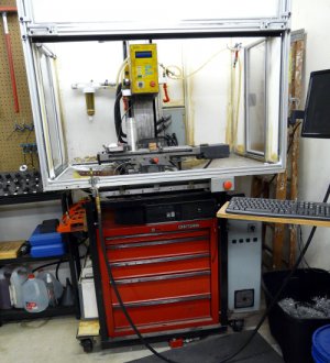
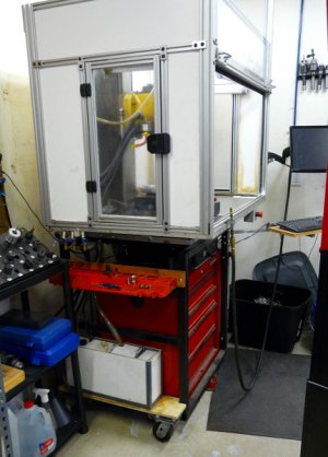
Stand is made from 1.5" medium wall square tubing. Right side is a NEMA box to house electronics (with thermostat controlled fans that I don't think have ever come on in 5 years). At the front center, on the floor is a barely visible pancake hydraulic cylinder (red). There is another cylinder under each rear corner. On the left rear (mid-height) are 3 ball valves that control & lock the oil flow to each cylinder individually. Oil pressure is supplied from a port-o-power type hand pump which is detachable after mill leveling is done. (Works good to tilt the pan towards the coolant outlet hole for fast emptying.) High grade casters make for very easy moving.
Enclosure is made from commercially available extruded aluminum attached to a home built aluminum pan. Side panels are PVC sheet. I've had a lot of trouble keeping coolant from dripping on to the floor. The PVC and aluminum framework need sealed better. I've tried all sorts of sealants (as evident with the yellowed joints, but the coolant always seems to win. I recently tried a new type of silicone that seems encouraging. Will see how that works with time.
Spindle is not installed in the mill in these pictures. It is getting new class 7 bearings.
View attachment 249244
View attachment 249245
I've used that on engines and the like but never thought to try it on the enclosure. I might even have some sitting on the shelf. I'll give it a try.Go to your local auto parts store and get some "Right Stuff" sealant. I used it on my enclosure and have zero leaks.


