- Joined
- Nov 23, 2014
- Messages
- 2,606
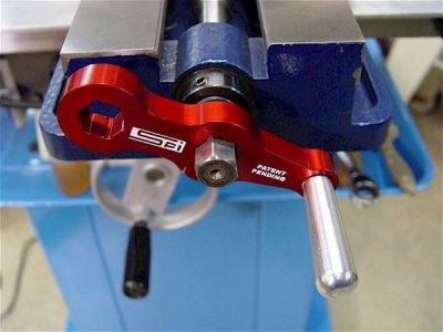
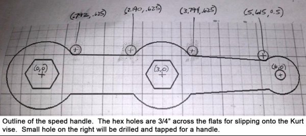
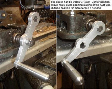
I love the Kurt vises on my Bridgeport and Jet mills, but I’m not a big fan of the crank handle. I forgot to shoot a picture of it, but they both have the standard “breaker bar” style handle. Works great for cranking down hard on the vise, but not so great for rapid moving of the vise jaws. I was shopping on eBay and saw a couple of designs for “speedy” handles. One has three crank rods on it like a drill press. Other was a piece of aluminum with a couple of ¾” hex holes spaced 3” apart. The center hole gives a 3” crank radius which makes for really quick spinning of the vise handle. If more clamping torque is needed, the handle can be slipped off the vise and positioned to the outside hex hole for more torque.
My BP has a 30+ year old Anilam Crusader II 2-axis CNC controller on it. Perfect application for this type of project. My wife helped me out with the location of the points for the ¾” hex holes (she’s a Unigraphics designer). I drew up the shape using a free CAD/CAM program called Techne CAD/CAM. Drew a ¼” circle at the corners of the ¾” hub radii to the straight lines and wrote a CNC routine to walk around and shape the handle.
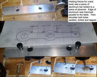
First step was to make a holding fixture for the crank handle blanks. I trued up the edge of a piece of aluminum bar stock and screwed it to a piece of plywood. The trued edge was trammed in line with the table and clamped in place. Plan was to mount the handle blanks to the holding fixture with 3/8” shoulder bolts spaced 6” apart. Holes were spotted, drilled and tapped for the shoulder bolts.
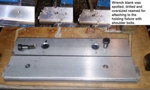
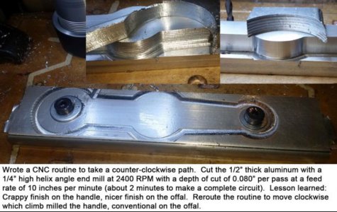
Blanks were made by spotting, drilling and oversize reaming (0.376”) two holes 6.000” apart. The blank was bolted to the holding fixture with 3/8” shoulder bolts and the outside CNC routine run to shape the part. I used a ¼” high-helix angle (for aluminum) end mill for the cutting and ran the BP at 2400 RPM at a feed rate of 10 ipm at a depth of cut of 0.080” per pass. Each circuit took about 2 minutes to make it around the perimeter.
Much to my dismay, the finish on the handle edge was pretty poor. I wrote the routine to run counter-clockwise around the handle which conventionally milled the edge. The scrap pieces had a really nice finish, they were cut by climb milling. So I rewrote the routine to move clockwise and got a much improved finish.
As an aside, my Anilam Crusader does have cutter compensation in its programming. A smart person would actually take the time to read the manual and learn this process. It would allow me to program the path directly and not have to manually calculate the offset for a particular diameter end mill. It also lets the routine run with a pre-programmed offset from the path (0.010” for example), then run a full depth finishing pass for a nice finish. Definitely a winter project to learn the programming better.
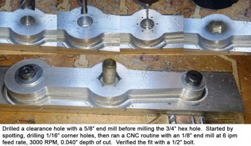
The hex holes were done via CNC also. Started with a 5/8” clearance hole in the center with an end mill. Then ran a routine that stopped at each of the 6 corners of the ¾” hex hole. Spotted and drilled to full depth with a 1/16” drill bit. Used an 1/8” carbide end mill for the cutting. Ran the BP at 3000 RPM with a feed rate of 6 ipm and a 0.040” depth of cut. Verified the hole size with a ½” bolt.
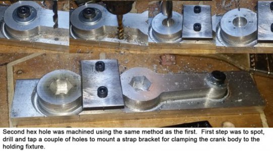
Had to remove the outside hex hole shoulder bolt to cut that ¾” hex hole. Spotted, drilled and tapped a couple of holes on the outside of the handle for clamp bolts. Clamped the handle blank to the fixture with a piece of strap steel and pulled the shoulder bolt. Used the same routines on the outside hole as the center hex hole. Then broke the crank edges with a table top belt sander. Drilled out the 3/8” handle hole with a 27/64” drill bit and tapped a ½”-13 hole for the crank handle.
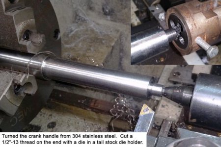
I made the crank handle out of a 1 3/16” round of 304 stainless steel. Turned it down to 1.000”, then turned a ½” deep shoulder to 0.495” dameter. Threaded the end with a ½”-13 die held in a tail stock die holder.
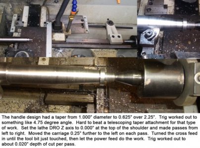
The design called for a 1.000” OD with a taper down to 0.625” at the handle base over 2.25”. Trig worked out to a 4.75 degree angle. My Grizzly G0709 has a telescoping taper attachment which is ideal for this type of work. The lathe also has a DRO on it. The tool bit was zero’d on the top of the base flange and passes were made from the left to the right. The carriage was moved an additional 0.25” to the left at the start of each path; cross feed was advanced until the tool bit just touched the handle. Trig worked out to a depth of cut of 0.021” per pass; finish was excellent.
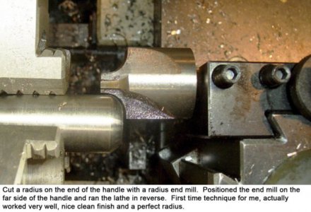
The blank was parted, flipped and faced. I cut a 3/8” radius on the end of the handle using a radius end mill. Mounted the end mill in a QCTP holder and position the cutter on the far side of the handle. Ran the lathe in reverse for the cutting. This is the first time I’ve used this technique, it worked great even on 304 stainless. I do see a radius/ball turning tool in my future however.
Put a dab of Loctite on the handle threads and cranked it home. The speed handle works GREAT! So much nicer than the standard breaker bar style handle. Nice thing about the CNC is it’s easy to make two which I did so my BP and Jet mills are now sporting new speedy cranks. The speedy handle design I copied off eBay is available for under $30 shipped. I spent around 5 hours to make two of them, so probably would have been smarter to just buy them but what's the fun in that!
Bruce


