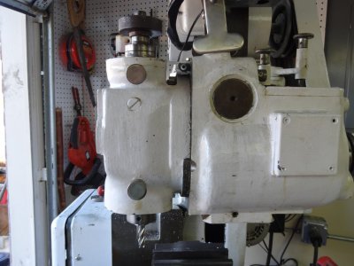
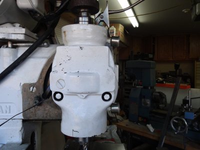
Need shape of the key in the Spindle that fits to the collet (Van Norman #12)

Junkmaster

Active User
Registered
Joined
Sep 3, 2012
Messages
51
Hello All,

My VN12 started producing a very poor finish. After a little inspection I found the key in the spindle which fits into the slot on the outside of the collet had broken and was forcing the collet off center.

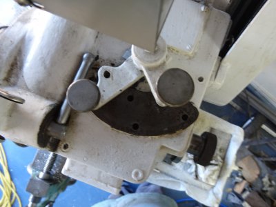
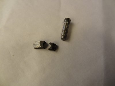
The key appears to be pretty well worn, so I don't know what it looked like originally. I'd gladly accept a photo or a rough sketch. I've attached a photo of the remains of my key & the pin that held it.

Evan R.
002.JPG
 
Last edited by a moderator:
Hello All,

My VN12 started producing a very poor finish. After a little inspection I found the key in the spindle which fits into the slot on the outside of the collet had broken and was forcing the collet off center.

The key appears to be pretty well worn, so I don't know what it looked like originally. I'd gladly accept a photo or a rough sketch. I've attached a photo of the remains of my key & the pin that held it.

Evan R.
Hi Evan,

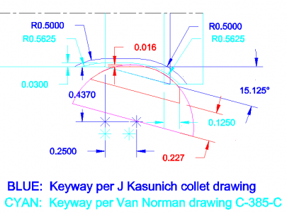
Here's a drawing of the keyway and key that I drew some time back:
VN C collet key - rev1.png

You can make the key from a #608 Woodruff key or a 3/16" chunk of 1/2" bar. The tit (which is what the pin is called) is optional. Most guys don't bother with them. As you can see from the drawing, there is a fair amount of variation in the keyway in the collets. The magenta lines are the shape of the #608 key; the red lines are the shape of the key.

The key is called an E-37½ key. You can buy one from RPI (http://www.repair-parts-inc.com/) for about $30.

Cal

VN C collet key - rev1.png
 
Thanks Cal, much more than I expected. I couldn't wait (excitement) to play with the machine, so reverse engineered what would fit and allow the collet to still seat.
I ended up drilling and taping a 4mm x 0.7mm thread through the key stock, then using an allen head screw thru the side of the spindle to pull the key into place. I filed the screw flush with the key on inside of the bore. The Allen head sticks out at an angle and looks wrong but is functional.

I'm researching the threads on rebuilding the spindle head. Fixing the key did not fix the horrible finish I'm getting.

As a sanity check let me ask some more questions. I mounted up a piece of 1/2 drill rod in the 1/2 collet and tightened everything down. I put a dial indicator against the drill rod. When I push on the drill rod I get 0.005" movement on the dial. When I pull on the drill rod I get 0.004". If I add the two together I'm getting 0.009" of movement in the spindle. I think this is way too much movement. I was hoping for 0.001 - 0.003.

Should I consider rebuilding the spindle head? I really like this machine. It is just the right size. So I'm going to do what it takes to make it work.
I've got the Van Normal Manual for the VN 12 that has the exploded diagram of the spindle. I'm going to go read the old threads. I read them a year ago and vaguely remember Cal giving pointers about something or another.

Again, thanks for the great diagram Cal. Now I can make a key the way it was supposed to be made.

Evan R.
 
Re: surface finish problems (Van Norman #12)

... Fixing the key did not fix the horrible finish I'm getting.

As a sanity check let me ask some more questions. I mounted up a piece of 1/2 drill rod in the 1/2 collet and tightened everything down. I put a dial indicator against the drill rod. When I push on the drill rod I get 0.005" movement on the dial. When I pull on the drill rod I get 0.004". If I add the two together I'm getting 0.009" of movement in the spindle. I think this is way too much movement. I was hoping for 0.001 - 0.003.
...
Hi Evan,

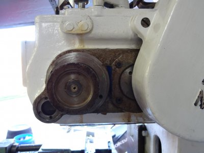
Van Norman mills use tapered roller bearings in the heads. Hopefully we can adjust out the excessive backlash. There were about 5 different cutter-heads used over time. Please post a photo of your cutter-head and the right side of your ram gearbox so that I can see what you have.

Cal
 
Re: Adjusting Spindle Bearing End-Play (Van Norman #12)

Hi Evan,

Here's the procedure of checking and adjusting the spindle bearing end-play, from the No. 16 manual:
If desired, the end play in the spindle bearings may be checked after a few months of operation in the following manner: Using a lead or composition hammer, gently tap the face of the spindle until all play is taken up towards the rear of the machine. Place an indicator against the face, and then tap the spindle shaft forward from the rear. If the play exceeds .001”, adjustment may be made as follows:


  1. [*=2]Remove the rear cap from the cutterhead.
    [*=2]Loosen the lock washer from the adjusting nut.
    [*=2]Loosen or tighten the nut as necessary to secure the desired adjustment.
    [*=2]Reset the lockwasher and reassemble the rear cap on the cutterhead.

As far as I know, the 0.001" play should be the same for a No. 12; I've not seen anything specifically for the No. 12. The cutter-head should be horizontal for checking the end-play. Before tapping the rear of the spindle, lift the tip of your indicator off of the spindle so you don't damage the indicator.

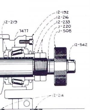
The adjustment instructions don't apply to your machine. Here's a section of the diagram for your cutter-head, showing the rear spindle bearing:
VN12_10 rear spindle bearing detail.jpg

The two rings, part number 12-233, are what control the end-play on the bearings. Loosen the back ring, which acts as a lock nut, adjust the front ring to get the desired end-play, and then tighten the back ring against the front ring to keep it from moving. Always recheck the end-play after tightening the lock ring.

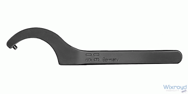
You need two hook spanners with pin noses, similar to the one below, to adjust the rings:

9545d.gif

What's your serial number? (Look at the top of the vertical dovetail for the knee.)

Cal

VN12_10 rear spindle bearing detail.jpg 9545d.gif
 
As always, thanks for the information and the time to enter it.

I measured the end play at 0.014. So adjustment is definitely needed.
I don't have the spanner wrenches on hand, I think I know where to get them in the morning. I'll give an update after the adjustment.

Evan
 
Whoooo Hooooo!

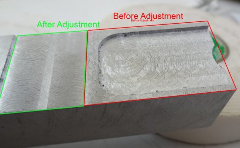
Success. I cut the same piece of aluminum before and after adjusting the bearings.
FinishComparison_reduced.jpg
The cut is still not perfect, but I didn't tram head, just swung it vertical, tighten the bolts and started cutting.


I went to purchase the 2" pin spanner and found out how much they cost. Just couldn't part with that much money for something so simple. And I needed two of them. Twenty minutes on the drill press and angle grinder I had two substitute pin spanners.

PinSpanners_reduced.jpg
Again Thanks for all info Cal, you saved another VN-12.

Evan R.

FinishComparison_reduced.jpg PinSpanners_reduced.jpg
 
Hi Evan,

I'm glad that worked. Nice job on the hook spanners.

You shouldn't need to tram your No. 12 every time you change the head; that's one of the nice features of the machine.

Cal
 
In the 18 months I've had the machine I had never taken it out of the vertical position. When I did a lot of swarf was wedged high up in the T-slot.
I cleaned out the swarf. Now, it seems that it may be just a hair off vertical by the shape of the crescents on the surface finish.
I'll try to improve the finish. I suspect some fine adjustment of the stops will be necessary. If I can't improve the finish still use it for the heavy removal of metal.

A project in my future is making an overarm support and some arbors for horz. milling.

As always, many thanks to you for your generous support of these cool old machines.

Evan R.
 
Back
Top