Thanks for replying U-Dr.
Can you help me determine the approximate diameter the motor pulley should be, if used with the existing driven pulley (the one with the clutch attached). (I do think that the cog, or timing type belt is a better alternative, but I know that I can't fabricate one and haven't researched what sizes are available) Not being an engineer, I don't know what RPM range that the DC motor would be happiest when turning from extremely slow speeds up to a maximum of about 2000 RPM or so ( thinking that most of my turning is usually at 200-600 RPM). I would think that there would be an ideal range, but then, that's why I got to the pros like you! Thanks in advance.
Hi John
the pulley arrangement should mimic a normal drive system. with a small motor pulley and a larger driven pulley.
although the dc motor will have a greater operational envelope, you don't want to overspeed the lathe in a near 1:1 drive ratio.
you should measure the largest spindle pulley then divide that size by approximately 3 or 4 for the drive pulley
the 4:1 running slower than the 3:1
obviously you could go larger or smaller on the drive pulley.
a word of caution as the drive pulley increases in size, the effective spindle speed will increase
you don't want a 4" chuck spinning at 3000 rpm, unintentionally.
the dc motor is happy under a lot of conditions thanks to the controller
200-600 rpms is a good range to plan for for spindle speed, the motor will cover all ranges in between and more.
fabricating cog pulleys can be done, but may prove to be a challenge for a beginner.
but if you have the tooling and the will- Nothing is impossible!!!
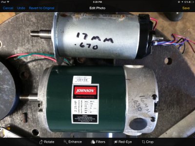
 Ok, after trolling several Facebook (for sale or free) sites I have acquired 2 2.25 HP DC motors from treadmills to replace the AC motor on my Jet 9X20 lathe. I collected the wiring, controller boards, etc. from two treadmills but really like the idea of a stand alone controller that can (hopefully) vary the spindle speed and I can wire to have capability to reverse it as well. One of the motors (a Johnson brand) is considerably larger than the other, so in my mind it will be a more robust unit than the other. (See pics) my questions are: what controller would be best for my intended purposes, and what pulley system (either purchased or turned) would be best to get the horsepower to my lathe? I sorta like the idea of a linked belt system (like the Fenner system) but don't want to have a slipping problem. Can these belt systems be doubled up..kinda side by side..and are the pulley systems flat with a guide on the sides or do they use a v-belt type pulley? I know, a lot of questions but I'm pretty new to this machining game.
