- Joined
- Dec 29, 2012
- Messages
- 394
DECLARATION
I’m in no way an electronics expert and all modifications I have made to the board (and the rest of my machines) are based on research, common sense and experimentation.
I upload my modifications here for educational purposes only.
It is neither the best nor the only way to do things.
I adopt Jumps’4 statement: “The way I did it”.
On the other hand, if you wish to follow my mods, there is no guarantee that the board you have (or will buy) would be the same design as mine!
WARNING!
The modifications deal with electricity and machines that can cause fire, injury or death if you treat them carelessly!
MY APPROACH
The way I have dealt with the matter “CNC my machine” was (is) a slow one. It started years ago and has gone long way since. I’m a hobbyist and I enjoy doing things “driving in the slow lane” gaining knowledge and experience all the way.
----------------------------------------------------------------------
Aiming to CNC my Sieg Super X2 Plus solid column mill I started almost two years ago to buy parts from e-bay. The first think I bought was a TB6560 3 Axis CNC 3.5A Stepper Motor Driver Controller Board and three NEMA 23 motors 175 Oz/in, 2.8A, 2.5mH (marked as 57BYGH56-401A).
As soon the board arrived I decided to test it and powered it up using a 12 volts computer PSU. The result was instant SMOKE coming from all 3 ICs on the board. When I complained to the supplier he replaced it instantly for a new one without asking any questions (??) or to send the board back.
This instant blow up of the board and the “very friendly” attitude of the seller to replace the board (without even opening a case at e-bay) made me suspicious and when the new one arrived I never connected it to the power supply but I started seeking information on those boards.
After reading many posts at other forums, studied the Toshiba TB6560 datasheet carefully and experimenting for more than a year with the board, I am convinced that this board is a poor design that needs some serious modifications to work as it should.
THE 3 AXES TB6560AHQ BOARD
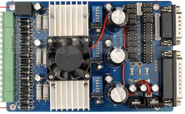
PROS
It is cheap (less than $ 50)
it can drive stepper motors up to 3Amps
It can handle up to 34 volts for the stepper motors.
CONS
There is no schematic for the circuit (some people created a schematic through reverse engineering though)
There is no true user manual (the one supplied is written in chinglish)
The designers violated most of chip manufacturers suggestions
Dealing with it could be very educational in terms of electronics principles and applications, but can give you many disappointments and could bring out very bad attitudes and behaviours towards other people and materials around you.
Why I chose to deal with it?
First of all I found myself possessing two of them boards (after the supplier replaced the broken one for free and after I have changed the ICs for $9 on the broken one)
Second, I love challenges (this one drove me to my limits though), and I love designing and fixing things
Third, I intent to use it for hobby reasons and I cannot afford a serious controller (like a Gecko one)
Fourth, every machine I bought “made in China” needed minor or major mods to operate as it should. Why this board should be an exception?
So I decided to try and make it work like it should.
ESSENTIAL MODIFICATIONS LIST:
1. NEVER power up the unit without motors connected to the outputs and do not unplug a motor when the board is powered up. The poor grounding (note2) may destroy the 6560 chips.
2. Ground the heat sink for each TB6560 through its mounting screws. In the current design, there is a danger of blowing all chips if one goes bad. Adding the grounds helps protect them all.
3. Disconnect the current reduction feature. This generates extra pulses and is not useful.
4. Pin 7 on driver chip has a cap that sets the internal frequency. Replace the 1000pf capacitor which is installed with a smaller value capacitor (150 to 330 pF).
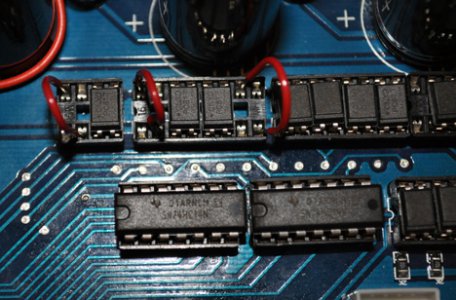
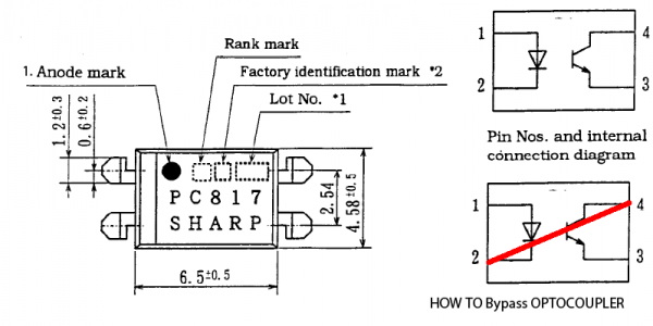
5. Clean up the pulse to Clock (Step) and Direction signals. The pulse coming from the computer through the optocouplers is very slow on rise time (because of the optocouplers). The chip misinterprets the signals and misses steps. Bypass optocouplers.
6. The way the ICs are getting power violates the manufacturers guidelines for power up and power down sequence. Do not use a single switch on the power line coming from the power supply. Either power the ICs on/off by a separate power supply or use a dedicated powerup/down circuit to deal with the sequence matter.
Step 2 GROUNDING HEAT SINKS OF TB6560AHQ CHIPS:
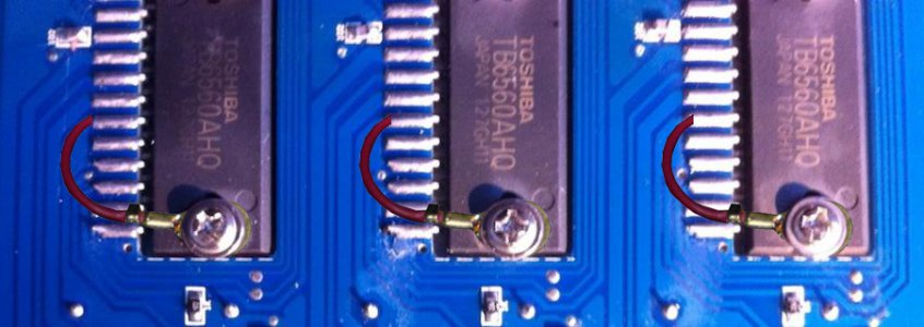
Heat sink Connected to pin 15 through the screw. The heat sink not being connected to GND.
The best way would be to connect a lead from one screw of every driver to the corresponding ground Pin 10 or/and 15 but NOT pin 6 (this is the 5V-GND - it should not be disturbed by additional driver currents!)
Step 3 CURRENT REDUCTION CIRCUIT REMOVAL:
Many people have disabled the “clever current reduction circuit” (which can't be that clever, as apparently it doesn't work well), a resistor a transistor and the capacitor that form the circuit have been removed. Resistor is silkscreened 4.7K. Transistor is further, on same trace and capacitor is connected to transistor.

Step 4 CHANGING THE OSCILLATOR FREQUENCY:
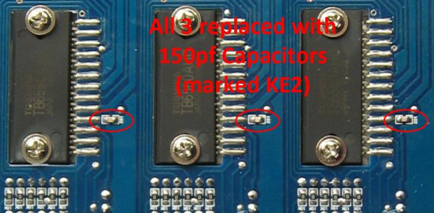
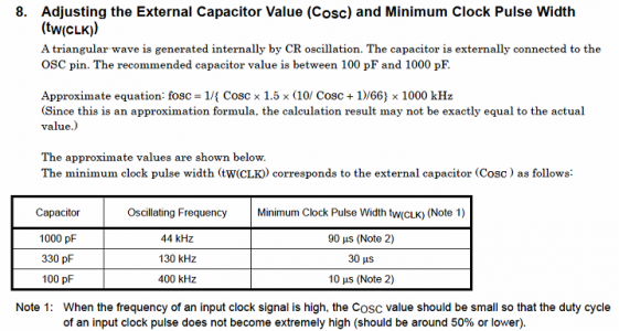
I have replaced capacitors on pin7 (silkscreened 102, i.e. 1000pF) with 3 smd capacitors salvaged from an old PC motherboard marked KE2 (i.e 150 pF). Toshiba recommends 100 to 3300 pF. The original 1000pf capacitor was putting the chopper frequency into the 40kHz region (330pf => 130kHz, 150pF ≈> 140kHz)
Toshiba notes at the TB6560 datasheet (p. 10)
Step 5 BYPASSING THE OPTOCOUPLERS:
SHARP PC817 optocouplers have a very slow response rate so they distort the incoming signals from the computer and allow system noise to cause unstable driver circuit operation.
According the datasheet the response time is as follows:

Moreover the way the optocouplers are in the circuit they provide no realistic isolation between the parallel port and the board so I don't see the point to use them. To solve the problems they create, I chose to bypass them.
Step 6 MAKING POWER DELAY ON & OFF CIRCUIT TO CONNECT IT TO THE BOARD
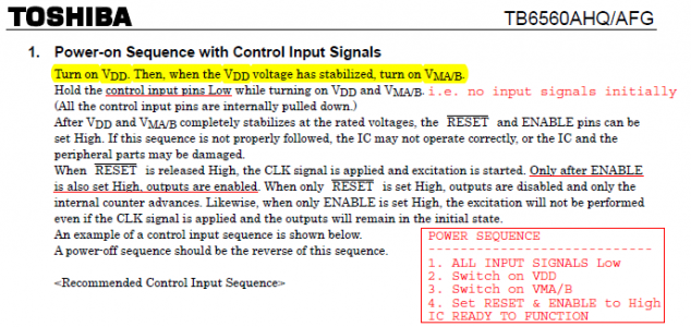
The 6560, according to the manufacturer (Toshiba) requires to get the 5V first and later it will accept the motor voltage
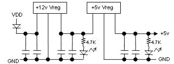
On my board the 6560 driver ICs are getting 12v and 5 v from the motor supply through 12 and 5v regulators respectively. This is a poor design as the 12V and 5 V regulators along with their capacitors perform a delay line for the 5V supply. It takes some milliseconds until the 5V is stable on the 6560 drivers. On the other hand, the Motor supply is directed to the drivers instantly.
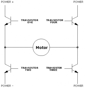
The transistors in the output driver are arranged in an H-bridge. It is essential to GUARANTEE at every time that within one pole of the H there is only one single transistor switched on at a time. This can not be done without the 5v being stable on the driver! So it is very probable that the too early voltage for the motor drive will open both transistors by itself and a short circuit will occur.
An extra problem seems to be if a motor output is not connected. My first 3 channel board was not connected to any motors. Thus all 3 ICs were blown instantly. This was promoted by the heat sink not being connected to GND.
DO NOT OPERATE YOUR BOARD WITH OPEN MOTOR TERMINALS. Connect spare motors or corresponding power resistors.
My design of a delay on & off circuit
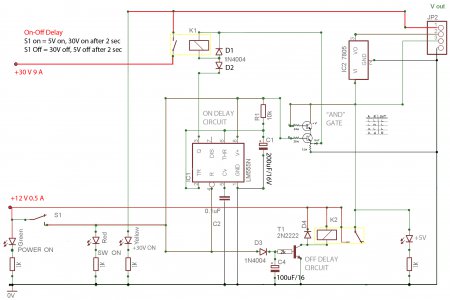
This circuit is designed to operate as follows:
When Switch S1 is turned to ON position, it turns 5V on instantly and gives a 2 sec delay to 30V power to the chip and when S1 is switched OFF it turns 30V off instantly and turns off 5V after 2 seconds.
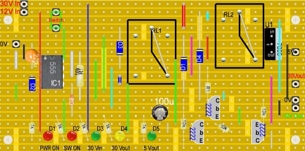
The circuit was constructed on the following stripboard for simplicity and ease of construction.
I have tested it and it works so far flawlessly.
After all these mods the board operates normally and there are no missing steps.
Thanks for reading this
Petros
I’m in no way an electronics expert and all modifications I have made to the board (and the rest of my machines) are based on research, common sense and experimentation.
I upload my modifications here for educational purposes only.
It is neither the best nor the only way to do things.
I adopt Jumps’4 statement: “The way I did it”.
On the other hand, if you wish to follow my mods, there is no guarantee that the board you have (or will buy) would be the same design as mine!
WARNING!
The modifications deal with electricity and machines that can cause fire, injury or death if you treat them carelessly!
MY APPROACH
The way I have dealt with the matter “CNC my machine” was (is) a slow one. It started years ago and has gone long way since. I’m a hobbyist and I enjoy doing things “driving in the slow lane” gaining knowledge and experience all the way.
There is a Greek poem named “Ithaka” that describes my approach:
When you set out for Ithaka ask that your way be long, full of adventure, full of instruction.
.....
Your arrival there is what you are destined for.
But don't in the least hurry the journey.
Better it last for years,
so that when you reach the island you are old,
rich with all you have gained on the way,
not expecting Ithaka to give you wealth.
....
So wise you have become, of such experience,
that already you'll have understood what these Ithakas mean.
(Constantine P. Cavafy 1863-1933)
Aiming to CNC my Sieg Super X2 Plus solid column mill I started almost two years ago to buy parts from e-bay. The first think I bought was a TB6560 3 Axis CNC 3.5A Stepper Motor Driver Controller Board and three NEMA 23 motors 175 Oz/in, 2.8A, 2.5mH (marked as 57BYGH56-401A).
As soon the board arrived I decided to test it and powered it up using a 12 volts computer PSU. The result was instant SMOKE coming from all 3 ICs on the board. When I complained to the supplier he replaced it instantly for a new one without asking any questions (??) or to send the board back.
This instant blow up of the board and the “very friendly” attitude of the seller to replace the board (without even opening a case at e-bay) made me suspicious and when the new one arrived I never connected it to the power supply but I started seeking information on those boards.
After reading many posts at other forums, studied the Toshiba TB6560 datasheet carefully and experimenting for more than a year with the board, I am convinced that this board is a poor design that needs some serious modifications to work as it should.
THE 3 AXES TB6560AHQ BOARD

PROS
It is cheap (less than $ 50)
it can drive stepper motors up to 3Amps
It can handle up to 34 volts for the stepper motors.
CONS
There is no schematic for the circuit (some people created a schematic through reverse engineering though)
There is no true user manual (the one supplied is written in chinglish)
The designers violated most of chip manufacturers suggestions
Dealing with it could be very educational in terms of electronics principles and applications, but can give you many disappointments and could bring out very bad attitudes and behaviours towards other people and materials around you.
Why I chose to deal with it?
First of all I found myself possessing two of them boards (after the supplier replaced the broken one for free and after I have changed the ICs for $9 on the broken one)
Second, I love challenges (this one drove me to my limits though), and I love designing and fixing things
Third, I intent to use it for hobby reasons and I cannot afford a serious controller (like a Gecko one)
Fourth, every machine I bought “made in China” needed minor or major mods to operate as it should. Why this board should be an exception?
So I decided to try and make it work like it should.
ESSENTIAL MODIFICATIONS LIST:
1. NEVER power up the unit without motors connected to the outputs and do not unplug a motor when the board is powered up. The poor grounding (note2) may destroy the 6560 chips.
2. Ground the heat sink for each TB6560 through its mounting screws. In the current design, there is a danger of blowing all chips if one goes bad. Adding the grounds helps protect them all.
3. Disconnect the current reduction feature. This generates extra pulses and is not useful.
4. Pin 7 on driver chip has a cap that sets the internal frequency. Replace the 1000pf capacitor which is installed with a smaller value capacitor (150 to 330 pF).
5. Clean up the pulse to Clock (Step) and Direction signals. The pulse coming from the computer through the optocouplers is very slow on rise time (because of the optocouplers). The chip misinterprets the signals and misses steps. Bypass optocouplers.
6. The way the ICs are getting power violates the manufacturers guidelines for power up and power down sequence. Do not use a single switch on the power line coming from the power supply. Either power the ICs on/off by a separate power supply or use a dedicated powerup/down circuit to deal with the sequence matter.
Step 2 GROUNDING HEAT SINKS OF TB6560AHQ CHIPS:
Heat sink Connected to pin 15 through the screw. The heat sink not being connected to GND.
The best way would be to connect a lead from one screw of every driver to the corresponding ground Pin 10 or/and 15 but NOT pin 6 (this is the 5V-GND - it should not be disturbed by additional driver currents!)

Step 3 CURRENT REDUCTION CIRCUIT REMOVAL:
Many people have disabled the “clever current reduction circuit” (which can't be that clever, as apparently it doesn't work well), a resistor a transistor and the capacitor that form the circuit have been removed. Resistor is silkscreened 4.7K. Transistor is further, on same trace and capacitor is connected to transistor.

Step 4 CHANGING THE OSCILLATOR FREQUENCY:
I have replaced capacitors on pin7 (silkscreened 102, i.e. 1000pF) with 3 smd capacitors salvaged from an old PC motherboard marked KE2 (i.e 150 pF). Toshiba recommends 100 to 3300 pF. The original 1000pf capacitor was putting the chopper frequency into the 40kHz region (330pf => 130kHz, 150pF ≈> 140kHz)

Toshiba notes at the TB6560 datasheet (p. 10)

Step 5 BYPASSING THE OPTOCOUPLERS:
SHARP PC817 optocouplers have a very slow response rate so they distort the incoming signals from the computer and allow system noise to cause unstable driver circuit operation.
According the datasheet the response time is as follows:

Moreover the way the optocouplers are in the circuit they provide no realistic isolation between the parallel port and the board so I don't see the point to use them. To solve the problems they create, I chose to bypass them.


Step 6 MAKING POWER DELAY ON & OFF CIRCUIT TO CONNECT IT TO THE BOARD
The 6560, according to the manufacturer (Toshiba) requires to get the 5V first and later it will accept the motor voltage

On my board the 6560 driver ICs are getting 12v and 5 v from the motor supply through 12 and 5v regulators respectively. This is a poor design as the 12V and 5 V regulators along with their capacitors perform a delay line for the 5V supply. It takes some milliseconds until the 5V is stable on the 6560 drivers. On the other hand, the Motor supply is directed to the drivers instantly.

The transistors in the output driver are arranged in an H-bridge. It is essential to GUARANTEE at every time that within one pole of the H there is only one single transistor switched on at a time. This can not be done without the 5v being stable on the driver! So it is very probable that the too early voltage for the motor drive will open both transistors by itself and a short circuit will occur.

An extra problem seems to be if a motor output is not connected. My first 3 channel board was not connected to any motors. Thus all 3 ICs were blown instantly. This was promoted by the heat sink not being connected to GND.
DO NOT OPERATE YOUR BOARD WITH OPEN MOTOR TERMINALS. Connect spare motors or corresponding power resistors.
My design of a delay on & off circuit

This circuit is designed to operate as follows:
When Switch S1 is turned to ON position, it turns 5V on instantly and gives a 2 sec delay to 30V power to the chip and when S1 is switched OFF it turns 30V off instantly and turns off 5V after 2 seconds.
The circuit was constructed on the following stripboard for simplicity and ease of construction.
I have tested it and it works so far flawlessly.

After all these mods the board operates normally and there are no missing steps.
Thanks for reading this
Petros
Last edited:

