Why Is American 220v Not Considered 2 Phase?

Superburban

Registered
Registered
Joined
Jan 2, 2016
Messages
1,953
A little thing that has always been bugging me. Here we have 220 volts by using 2 110 volt legs that are 180 degrees apart. Ie, load on 2 legs.

Much of Europe has 220 volts, but only on one leg, the other is neutral. Like our 110V setup, but 220 volts.

3 phase has power on three wires, makes sense to call it 3 phase.

Single phase 110V here (or 220V in much of Europe), only has the load on one wire. Again, it makes sense to call in single phase.
Following all that, it seems that our 220 Volts (110 on each leg), should be called 2 phase.
 
It's single phase because it comes off one winding in the transformer. We just center tap it to get the 120. 3 phase comes from 3 separate windings on the secondary of the transformer.
 
Ok, Thanks that makes sense. Is there any place that uses 2 phase?

Another similar question, how do they get the two legs in phase, when the power being generated is in 3 phase, and has the legs 120 degrees apart?

Thanks for the quick reply, and illustrations, they help.
 
It's single phase because it comes off one winding in the transformer. We just center tap it to get the 120. 3 phase comes from 3 separate windings on the secondary of the transformer.

I get it now, so residential only gets one leg from the power station, and it is converted to two hot legs at the transformer. I always thought residential got two legs out of the three phase.

Thanks
 
No, the primary feed to the transformer on the pole (at least mine) is 7200 VAC, single phase. There is one hot wire and a neutral run to it, with the neutral also being grounded by a copper wire running down the pole to a round plate on the bottom of the pole. So mos residential services, on my rural coop, run a simple 2 winding transformer, although I should mention that on the secondary, there are I believe 3 hot taps, so they can get the proper or closest voltage out on the secondary. This allows for some variation in the primary feed. It could be that one of the possible secondary taps runs at 260, one close to 240 (mine is close to 237), and one could be 190. So when they bring the service drop in, they make the best selection then.

If you look at the poles, some will have 3 hots on the top crossbar. That is all three phases. But in residential areas, normally you won't see all three, but often 2, so they have twice the capacity since they can use either one, whichever is loaded least, to add the next customer. But that represents 2 separate windings in a transformer upstream. So they are both full wave, single phase.
 
This came up before and someone said 2 phase was available in Philly?

R
 
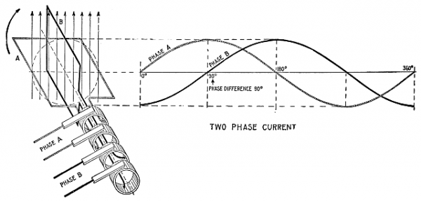
Yes, 2 phase is still in limited use. Wiki lists parts of Pensilvania as well as part of Connecticut as still using it. I think part of the confusion is that true 2 phase requires 4 conductors, 2 for each phase, whereas single phase is delivered with only 2, a hot and a neutral.

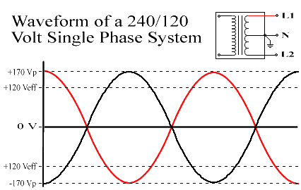
I think there is kind of a crossover in descriptive terms. When we have a center tapped transformer, we can properly call it "split phase", because half the winding provides "phase A" and the other half "phase B", so it's technically proper to call it "dual phase"or "split phase". Easy transition to "2 phase", but truly a little different animal. When you split a single phase, which contains the entire sine wave of a "phase", you only get either the voltage swing from zero to positive, with the peak of the sine wave at whatever voltage half the whole winding is providing, in our case here in the US, that's about 120VAC. Or, you could get the "other" half of the sine wave, which swings from zero to the "negative" peak, which reaches the same voltage as the other half. They are symmetrical. Then enter the time domain. There is a period on split single phase during which the voltage is zero. That's while the power swings to the other side of zero. So that pair of wires just waits while the other gets the other half of the sine wave. Think of zero being represented by the neutral wire. It's always at zero potential. Then all our comparisons reference that neutral as the mid-point of our entire phase cycle. So half the time each "hot" leg of our single phase system is at zero volts while the other leg gets the other peak and hence is hot. Then when you are using 240, and not using the neutral as a reference zero, there is only an infinitely small time when the voltage drops down the sine wave and crosses] the zero voltage line, but various factors make this "zero crossing" insignificant for most applications, like motors for instance. Then you properly measure the available voltage from "peak to peak" or "P-P". The reasons behind this are a little complicated, and I don't know enough about them to truly provide a good explanation.

Now, all the real electrical engineers can come in and clear up any details I have gotten wrong, or shoot the whole things down. If I have a gross misunderstanding of the subject, I hope they do. I'm sure they could at least add something, or maybe give a better explanation, but that's how I have it in my mind, anyway, for what that's worth .
 
Personally I think waveform diagrams like Jim Dawsons 240/120 although technically correct are maybe adding to the confusion. Typically 240 V motors have no connection to the neutral. Since the motor only has 2 connections if we were to arbitrarily choose one leg to call our zero volt reference, the waveform will look like a sine wave and except for the amplitude would be identical to what you would see on a 120V line. Voltage is relative and is always measured between two points, just like distance. To show a signal on a oscilloscope that looked like that diagram would require 3 connections (and an oscilloscope with multiple channels) because you would really be measuring 2 voltage signals referenced to neutral. Note that the motor itself only has 2 connections and only "sees" one voltage signal and that signal looks like a sine wave.

I have either made this clearer or totally muddied the waters, I'm not sure which :)
 
Well, to further complicate matters I have heard US power referred to as Edison 2 phase.
Now that makes little to no sense since Edison HATED AC and wanted DC in everyone's house with a small generator in a barn out back.
Tesla and Westinghouse partnered to create the system we all know today in the US so how Edison got involved is anyone's guess and may be totally incorrect. But I have heard that said a couple times referring to the 2 leg 180 degree out of phase 120/240 60Hz system we currently enjoy.
 
Back
Top