And so it begins!

I found a nice gear making script that runs under openSCAD. It's a little different because it uses SVG files produced by Inkscape, which has a built-in gear making app. In addition to creating the gear form, it adds text indicating the tooth count.

In addition, it gives you the option of stacking another gear on top if you frequently use a particular combination.

Here's what a single gear looks like in openSCAD's rendering window:

View attachment 492068
Is OpenSCAD the one where everything is done by command line or scripting?

The possibilities and power of that approach (given the granularity of control you must get) does sound fantastic. That said, I'm only really just getting the hang of basic FreeCAD usage. I have yet to install its gear workbench (FCGears?). :grin:
Yes, it's a script-based approach. It doesn't implement a "pure" object-oriented approach, where you can change the object properties at any time after it's been created. You must start out by creating a basic shape like a cube or cylinder, then successively modify it. So you will see a lot of program sections that may look like:

union{ difference { union { translate() {object1} translate() rotate() {object2} } {object3} } {object4} }.....

So it requires a certain amount of mental discipline to break your desired (final) object down into component parts that combine to form what you want. The difference operation removes material and the union operation combines shapes. There are other boolean operators like "intersection" but so far I haven't found it necessary to use it.

You can create functions and modules to create basic shapes, and then successively refine them. Modules are very handy for creating features that are tiresome to repeat, like countersunk holes.

Like any CAD program there is a learning curve. I personally find the scripting approach easier to use but you may not.

One drawback to openSCAD is that it isn't easy to get dimensions, or flat drawings, out of it. But if all you want is 3D prints, that's not a big deal.
That incremental approach is a comfortable fit with the concepts of parametric modelling.

Yeah, I'm a decent enough programmer (been doing it professionally for nearly 30 years; no rock star, but competent enough) but I reckon I can manage to do what I'll need to do for the forseeable with a UI based CAD program.

I do enjoy my work and I'm no stranger to popping back upstairs to my office in the evening, after a thought has popped into my head for an optimisation, or a cleaner, more elegant implementation, but ultimately, I'm paid for that and my work is billable.

Unpaid coding for me is rare these days and is only something I resort to when other, easier solutions have failed to provide a benefit*. So I'm not sure OpenSCAD is for me. ;)


*I'll probably end up writing some code when I add an ELS to my lathe; there are plenty of already written projects on github but fiddling with someone else's code is a good way to understand that code and its limitations, especially if its readability is less than...um...optimal.
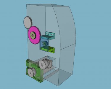
If you have any FreeCAD questions, there's a few of us that can help you out. I've used the gear workbench when I modeled my lathe for my ELS conversion. I was trying to work out what would fit. I decided that a timing belt would give me better options than a direct gearing from the spindle.
frontview_gears_tb.jpg
 
Last edited:
That incremental approach is a comfortable fit with the concepts of parametric modelling.

Yeah, I'm a decent enough programmer (been doing it professionally for nearly 30 years; no rock star, but competent enough) but I reckon I can manage to do what I'll need to do for the forseeable with a UI based CAD program.

I do enjoy my work and I'm no stranger to popping back upstairs to my office in the evening, after a thought has popped into my head for an optimisation, or a cleaner, more elegant implementation, but ultimately, I'm paid for that and my work is billable.

Unpaid coding for me is rare these days and is only something I resort to when other, easier solutions have failed to provide a benefit*. So I'm not sure OpenSCAD is for me. ;)


*I'll probably end up writing some code when I add an ELS to my lathe; there are plenty of already written projects on github but fiddling with someone else's code is a good way to understand that code and its limitations, especially if its readability is less than...um...optimal.
Sure, got that. But for a small example, here's something I worked on recently. It's a lamp holder for a single white LED, to serve as an illumination source for some LCD DROs on my benchtop mill.

The holder looks like this:
LED lampshade.png


And the code looks like this:

// LED lamp base for DRO illumination
FmaxIR = 4.4; //maximum flare inside radius, mm
FmaxOR = 7.4; // maximum flare outside radius
FminIR = 2.6; // minimum flare inside radius
FminOR = 5.6; // minimum flare outside radius
Fheight = 5; // height of flared portion
Bheight = 11; // height of body
Bh2 = 4; // length of base-compatible section
BIR1 = 5.1/2; // inside radius to accommodate LED body
BIR2 = 6.1/2; // inside radius to capture LED base

difference() { // make features for LED
union() {
translate([0,0,Fheight-.1]) cylinder(h= Bheight+.1, r1 = FminOR, r2 = FminOR, center = false, $fn = 40);
difference() { // make the flared portion
cylinder(h = Fheight, r1 = FmaxOR, r2 = FminOR, center = false, $fn = 40);
translate([0,0,-.2]) cylinder(h = Fheight+.1, r1 = FmaxIR, r2 = FminIR, center = false, $fn = 40);
} // end, difference for flare
} // end, union
translate([0,0,12]) cylinder(h=15, r1 = BIR2, r2 = BIR2, center = false, $fn = 40); // Center hole for LED, stopper for LED base
translate([0,0,-.5]) cylinder(h = 20, r1 = BIR1, r2 = BIR1, center = false, $fn = 40); // Center hole for LED, LED body.
} // end, difference for LED stuff

Dimensions are in mm. OpenSCAD doesn't know or care about Imperial or metric, they're just numbers. I render to an stl and then scale in the slicer.

It may look a bit obtuse but the elements are pretty simple. Cylinder objects are a bit complex because they permit you to specify the radius (or diameter) at the base and top, so it's easy to create tapered cylindrical items. As in this case.

The $fn parameter specifies the number of facets used to approximate the cylinder. More = smoother. But using very low values like $fn = 4 is a dead-simple way to create pyramids.

The code creates the flared and straight sections, and the center hole with a step to capture the base of the LED. There is a second piece that will be glued to the bottom, and it has an internal taper to match the nozzle end of an adjustable mist coolant-dispensing device. It was cheap and the center bore readily accommodates the wiring. The bottom end is a 1/2-20 threaded piece so it's easy to install wherever you want.
 
Sure, got that. But for a small example, here's something I worked on recently. It's a lamp holder for a single white LED, to serve as an illumination source for some LCD DROs on my benchtop mill.

The holder looks like this:
View attachment 492128

And the code looks like this:

// LED lamp base for DRO illumination
FmaxIR = 4.4; //maximum flare inside radius, mm
FmaxOR = 7.4; // maximum flare outside radius
FminIR = 2.6; // minimum flare inside radius
FminOR = 5.6; // minimum flare outside radius
Fheight = 5; // height of flared portion
Bheight = 11; // height of body
Bh2 = 4; // length of base-compatible section
BIR1 = 5.1/2; // inside radius to accommodate LED body
BIR2 = 6.1/2; // inside radius to capture LED base

difference() { // make features for LED
union() {
translate([0,0,Fheight-.1]) cylinder(h= Bheight+.1, r1 = FminOR, r2 = FminOR, center = false, $fn = 40);
difference() { // make the flared portion
cylinder(h = Fheight, r1 = FmaxOR, r2 = FminOR, center = false, $fn = 40);
translate([0,0,-.2]) cylinder(h = Fheight+.1, r1 = FmaxIR, r2 = FminIR, center = false, $fn = 40);
} // end, difference for flare
} // end, union
translate([0,0,12]) cylinder(h=15, r1 = BIR2, r2 = BIR2, center = false, $fn = 40); // Center hole for LED, stopper for LED base
translate([0,0,-.5]) cylinder(h = 20, r1 = BIR1, r2 = BIR1, center = false, $fn = 40); // Center hole for LED, LED body.
} // end, difference for LED stuff

Dimensions are in mm. OpenSCAD doesn't know or care about Imperial or metric, they're just numbers. I render to an stl and then scale in the slicer.

It may look a bit obtuse but the elements are pretty simple. Cylinder objects are a bit complex because they permit you to specify the radius (or diameter) at the base and top, so it's easy to create tapered cylindrical items. As in this case.

The $fn parameter specifies the number of facets used to approximate the cylinder. More = smoother. But using very low values like $fn = 4 is a dead-simple way to create pyramids.

The code creates the flared and straight sections, and the center hole with a step to capture the base of the LED. There is a second piece that will be glued to the bottom, and it has an internal taper to match the nozzle end of an adjustable mist coolant-dispensing device. It was cheap and the center bore readily accommodates the wiring. The bottom end is a 1/2-20 threaded piece so it's easy to install wherever you want.
Cripes that looks like a lot of work.
I could have that modeled in Fusion360 or Solidworks before you got to the 3rd line. I get that one can become proficient at command line programming, but that is crazy.
If that is what you are good at, then you do you.
 
Back
Top