Tool and cutter grinder build

I decided to get busy on the rocker arm today. I wanted to go to a friend's and do it with a boring head, but that didn't work out, so I bored it with a fly cutter and got it to within .001". ( fly cutters make good boring heads, just hard to set.)milling rocker arm.jpg
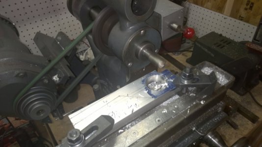
Once the hole was bored, I started to mill the end for the pinch clamp and slot it also.
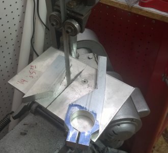
cutting out the rocker arm.jpg
I cut t he rough shape out on the band saw and cleaned it up on the mill.
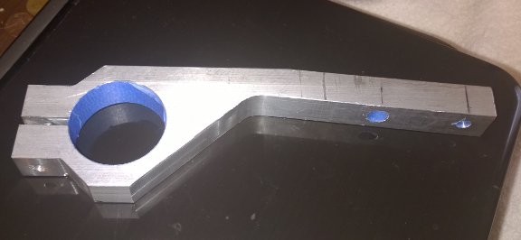
rocker arm ready to paint.jpg
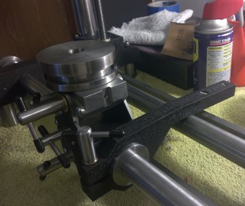
After cleaning up on the mill, drilled a couple holes and masked it to be painted with the wrinkle finish. The next two photos show the rocker arm all finished and installed on the grinder.
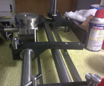
rocker arm.jpg roker arm2.jpg
Tomorrow I hope to get started on the micrometer adjustment for the rocker arm. the very last out board hole is for a counter weight. I wanted this brass , but a 2" diameter x 2" long piece of brass is extinct around here, so it will be made of CRS. I am thinking of dressing it up with a couple of bands of knurled finish. We will see how it looks tomorrow. I wanted the micrometer to be brass too, but it is way too expensive as it is 1 1/2" diameter and 1 1/2" long.( plus the largest brass found locally is 3/8" rod and they want $28 for three feet):eek:
 
I started out building a Bonelle grinder with a couple features borrowed from the Quorn.

That said, as I progressed, I have completely abandoned the Bonelle prints and am building what I want in my grinder. As I went along I found short comings in the Bonelle and the Quorn as to features I desired , (so I made changes). There have been many changes, big and small since the start, but I will end up with the machine I want , with all the features I want. I make new prints for my changes so when completed , I will have a complete set of prints to match what I built.

I am also keeping a separate build log with information and all the photos step by step. ( it is up to 41 pages so far). When the grinder is completed, this build article, (if you will), will be converted to a PDF document and made available to anyone that wants it , along with a set of the prints. Just ask when the grinder is complete if you wish to receive them.( If possible to post them on this site, I would rather do that)

Some of the changes made so far include
  • A less complex micrometer setup on the front bar
  • Ball bearings and thrust bearings in the micrometer to reduce friction and make it work smoother.
  • The bed was lengthened from 12" to 20"
  • The column height was increased from 11" to 15"
  • The sliding base and work head was increased slightly in size and made heavier.
  • The rocking arm was increased in size to be a little heavier and sturdier.
  • An adjustable stop will replace the fixed stop the other grinders had to limit the tilt of the work head away from the wheel.
  • The work head is made larger and to use 5C collets.
  • The spindle arms slide in and out to adjust the fore and aft position of the grinding wheel to the front bar ( the other grinders lacked this feature).
  • A simpler acme screw and nut was used for the wheel head elevation mechanism. It is positionable in .001" increments. easier to build , and smoother operating.
  • A larger HP, more powerful high speed motor was acquired at a very low cost ($30 new) , but is still about the size of the popular motor used (at $300 to $500).
  • The spindle inversion feature ( the other grinders had this) will still be possible , but with less tear down of the machine to set it up. ( this is probably rarely used, but I wanted the capability. )

I have some more changes planned but haven't got them built yet.

The spindle is the last major component of this grinder to build. I have all the parts , just have to start it. I have been trying to get a lot of details wrapped up.

Some one asked me what this machine was called ( so, I guess I have to come up with a name for this thing)
 
Hi

Try


The Frazier Expansion

or

Enhancement

Development

Perfection

Correction
 
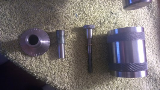
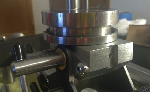
Today I made the counterweight for the rocking arm. It may be a tad too heavy, but I can saw some off easier than add it back on. I will check it when the whole machine is assembled. It should help balance the weight of the tool holder when rocking it in or out past the wheel. I also made some of the micrometer parts for the rocking arm.
counter weight and micrometer parts.jpg
These are the parts I made today. I'm getting pretty good at putting the graduations on dials. Now if I could get better at stamping the numbers.
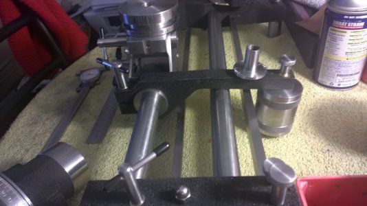
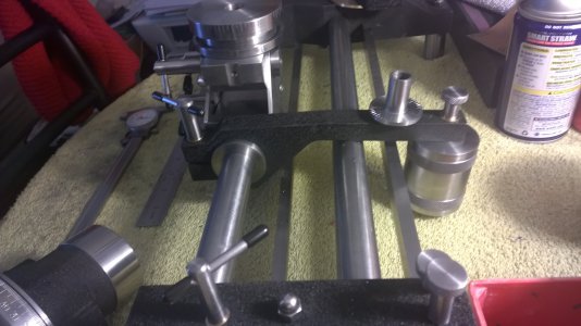
micrometer and counterweight installed2.jpg
These two photos show the counterweight installed and the micrometer installed. I still have to make the adjustable pin for the micrometer. The distance of the micrometer on the arm is close to the distance of the tool from the front bar so the micrometer readings will be reasonably close to the offset of the tool.

One other thing I did today was put the graduations on the rotary base table. It still needs the numbers stamped, but I was not in the mood to try that today.
table graduations.jpg I marked it every 5 degrees. The 3 inch diameter is too difficult to get 360 marks on as they are so close together, and I probably can't see them that close.
 
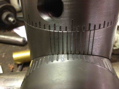
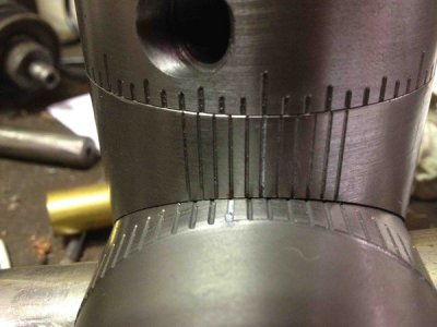
A picture is worth a thousand words Mark.
IMG_0331.jpg
The top and bottom dials are at 5 deg. In the space of 5 divisions on the main you divide the vernier into 6. When your on a 5 deg mark two lines of the verier line up, then at 1 deg and so on only one does. I engraved the vernier on either side of the zero mark but one side would work just as well.

Greg
For some reason, I am still lost. I tried this once before and I just can't get my brain to understand it.
 
Back
Top