Brush Or Brushless Motor For A Mini/midi Lathe?

A Brushed Motor has a rotating set of wound wire coils called an armature which acts as an electromagnet with two poles. A mechanical rotary switch called a commutator reverses the direction of the electric current twice every cycle, to flow through the armature so that the poles of the electromagnet push and pull against the permanent magnets on the outside of the motor. As the poles of the armature electromagnet pass the poles of the permanent magnets, the commutator reverses the polarity of the armature electromagnet. During the instant of switching polarity, inertia keeps the classical motor going in the proper direction.
Note that this is a simplified version of a DC motor. Practical ones have many poles and many commutator segments.
 
Note that this is a simplified version of a DC motor. Practical ones have many poles and many commutator segments.
Correct, and so can BLDC motors. There are many variations on poles, wingdings, etc., and this can significantly affect their performance and characteristics of the DC motor. In this case it is doubtful one would see an appreciable difference in the context of this post/specific application. I would expect the BLDC motor to perform better over a wider range, but there are a lot of variables. Same applies for VFD driven 3 phase motors, there can be very wide performance variations between 3 phase motors and also the VFD used.
 
Maybe a few pictures would help. It seems that there may be some confusion and I hope this helps.
Without getting into the physics and math on why these are true I'll provide a top level picture.

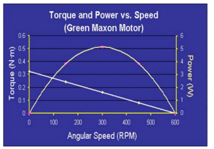
In a conventional induction or brushed motor the torque decreases with speed and is nearly linear between the stall torque and the max rpm.
The delivered power is the product of the speed and torque and the power peaks near the maximum unloaded speed.
The maximum rpm is where the back emf equals the supply voltage.

upload_2017-4-20_12-32-33.png

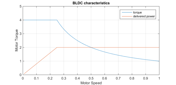
Below is the characteristics of a BLDC motor with proper control.
At low RPM, the torque is limited by the coil resistance power dissipation.
Above some critical speed the torque starts to drop inversely with the speed but the delivered power is the
maximum the motor can deliver for it size and is nearly constant over most of the possible operating range.
The curves have been exaggerated some for illustration and does not correspond to a real motor.

The net effect is that this is close to the characteristics of a conventional motor if the motor was kept at the maximum
delivery power using a transmission or other speed conversion method.

This is why most machines with BLDC's on have 1 or 2 gear ratios. The electronic controller effectively does the
work of a transmission over most of the range.

A more sophisticated controller could allow larger torque outputs at low speed as long as the average dissipated
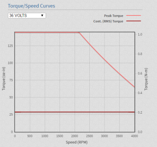
power or case temperature does not exceed the design limit. Many BLDC's specify the rms torque vs. speed similar what is below
and another peak torque curve (maximum torque possible over short time spans).

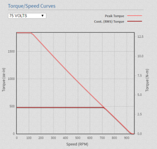
The next curve is from the data sheet of a real BLDC. (teknic clear path CPM-MCVC-3441S-RL)
The curve is somewhat different as this motor spec includes the controller behavior, but is similar with the BLDC characteristics.
The knee in the second figure near 700 rpm is where the back emf starts to limit the torque (vs. power dissipation) and at 925 rpm the torque is 0 and this
is where the back emf equals the supply voltage limit. (not shown before). this 0 torque speed is present in the traditional motors
and applies to all types.

upload_2017-4-20_12-48-50.png

upload_2017-4-20_12-56-42.png

upload_2017-4-20_12-30-28.png
 
Back
Top