A Vertical Slide For A 9x20 Lathe

Had a better day today.
I cleaned up the horrible thread with a small triangular file till it fit, its still horrible with torn bits but it does work and as the section it screws into has a long thread its actually quite smooth in action much to my surprise.
At least I now have real measurements to make a new one from. (gotta look on the bright side.
lead-screw-2.jpg

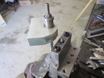
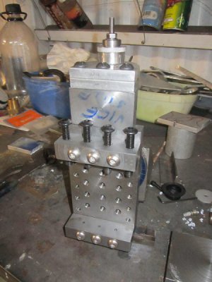
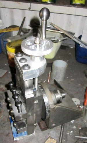
All screwed up, the top aluminium section with the bearings will bolt to the top of the plate with all the mounting holes.
lead-screw-1.jpg
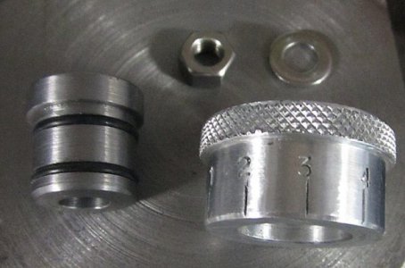
The small top hat section clamps to the centre of the top roller bearing and will have a round dial marked in 1/10's with a friction sliding fit so if I need to be accurate with the slides movement I can.
The handle (when I can decide upon a shape) will be pinned to the top of the top hat and held with the dome nut.
Now back to the gibbs.
 
Last edited:
Next to set out the holes for the top bracket.
I set all the parts up and used c/sunk screws to hold the slide plate in the correct position as the gibbs are not ready yet.
The centre bolt was turned to a point and the top bracket lowered via the lead screw, aligned and a mark made.
Drill, remove the point and move to the next hole, use the bolt to align and repeat till all three are done

bearings-setup-1.jpg

The top hat shape then had a couple of grooves added for "O" rings to add a tight friction fit to the knurled scale.
Each division is 1/10 of a millimetre movement.
o-rings.jpg
The movement is nice and smooth and the scale turns with the screw but can be manually set to the number.
Those three bolts pass down into the main slide block.
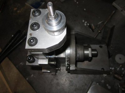
top-view.jpg

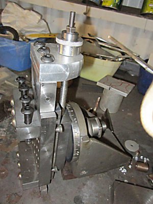
side-view.jpg

front-view.jpg

Hopefully if I'm allowed some shed time its the handle tomorrow.
I'm a tad concerned about the amount of metal hanging out from the cross slide so I may have to add some extra support once in place but am unsure how at this moment in time.
 
or some reason this post disappeared into the aether so I try again.
I was going to pin the top hat section to the shaft when I suddenly realised that the scale ring would prevent that DOH!
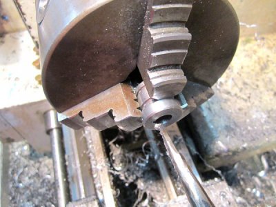
So I made a small cutter to broach out a keyway.
keycut1.jpg
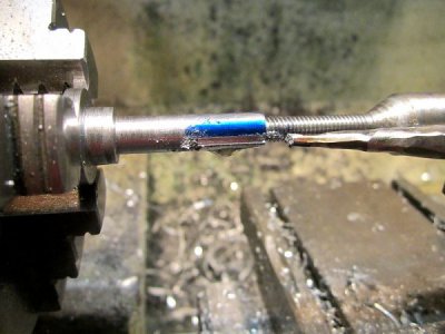
Flipped the broach over to key the shaft
keycut2.jpg
I suppose I could have continued the keyway along the threaded portion to key the handle as well but decided to use three pins instead.
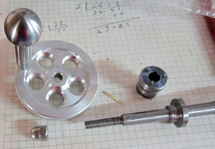
The handle is a rescue from another old project and as the ball end wouldn't unscrew I had to keep the length so I could grip it in the chuck as I didnt want to mar the shiny ball.
The disk was again a scrap that I drilled out five holes and knurled the edge. The small brass key was cut from a sheet and filed to size.
handle-bits.jpg

All back together and works very smoothly with the c/sunk screws instead of gibb strips. Almost to the point of just using those, but I wont.
handle-on.jpg

Now I just need some time to arrange the friends mill to finish the gibbs.
 
Gibbs and dovetail milled, assembled with "G" clamps and it works.
Only had an hour free so that was all I managed to do today.
 
That's amazing. Awesome fabricating.
Robert
 
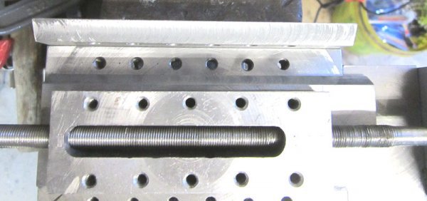
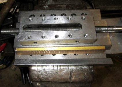
As the side without the adjusting screws had room to access the 6mm through threaded holes I used them to fix that dovetail.
A bit over the top maybe but no threading to do.
first-gibb.jpg

I'm not so lucky on the other side with the brass gibb strip as it occludes part of the existing holes.
You can see the six screws at the top of the unit.
The photo makes the dovetail that the brass is against look vertical but its actually cut at 30 degrees.
I will drill and tap new fixing holes between the existing holes but only halfway through the block at 5mm.
I guess this is what happens when the main drawings are just carried in your head.:bang head:

second-gibb.jpg
 
Nice job Savarin, you do some nice work, hard to believe your not formally trained. How long have you been self learning. It's quite amazing what you can make with just a lathe and a lot of ingenuity. you also have the advantage of not having been taught what can't or shouldn't be done, something I've had to unlearn when faced with that impossible job, learning to think outside the box is very useful at times.

Bob
Thanks Bob, Ive been making "stuff" all my life from a very early age with mecanno and other construction sets. I can visualise most things in 3d I just needed some basic tools to fabricate what I wanted.
This is my first lathe so I now have three years of basic machining experience that includes some monumental stuff ups but thats what learning is all about.
I used to tell my students that they can do anything, they just have to think first then have a go.
It didnt matter if it didnt work as they would still learn heaps. I try to live by this mantra.
 
My first vertical slide was a bit small in what it could hold so I have decided to build a larger one.
It should look something like this (but not in these colours:grin big:)
View attachment 134262
I faced and edged a chunk of hot rolled scrap for the front plate.
I will drill and thread a matrix of holes in this for a variety of mountings.
View attachment 134260
All four edges were also faced off in a similar manner and ended up within 0.001" of square on all sides and faces. It took a couple of attempts to get it this good.
View attachment 134257

Interesting, one of the first things we were taught at trade school was to face a hunk of steel on all sides and edges, keeping it square and flat. I see you've learned the process well. We eventually finished up with an engineer's "C" clamp, making all the parts by various processes.

the next job was to soak the 12mm plates for the angle and swivel plate in vinegar to remove the mill scale, 48 hours and it was cooked to perfection, a bit safer than hydrochloric acid.
View attachment 134263
The first mistake was to bore the plate for the swivel shaft too large, Doh! never mind, I just knurled the shaft to make it a tight fit. You can just see it there.
The worst part was how I managed to make it too large.
The shaft is 20mm, I turned down one end to 15mm which is where I wanted to fit the shaft.
I used the calipers to measure the shaft then checked that against some imperial drills, the first one I tried was larger than the set caliper gap so I said to myself - " no worries I can bore it out that little extra bit."
I have absolutely no idea why I thought this, definitely a senior moment.
I cut a large counter sink for extra weld holding. This side will eventually be faced flat.
View attachment 134261
First side welded but forgot to take a photo.
Second side to be deep welded.
View attachment 134264
I cut the corners off the circle with the angle grinder first to make it easier to turn round.

About time you got a bandsaw, that poor angle grinder does way too much cutting work. I recently got a Hafco Metalmaster BS-5V Bandsaw, Widely available in Aus. very happy with it, they have a range of models around that size.


View attachment 134258
I decided to turn it between centres to ensure the disk had parallel sides.
and that the shaft was at right angles.
View attachment 134259
I have decided to add a degree scale on the outside. I have no idea if this is worthwhile but it will look good.


To this end I have printed a degree scale onto a sheet of paper and stuck it to some stainless plate.
I will use this in the end of the main spindle to index the wheel.
View attachment 134256
This is printed at two degree intervals as I think one degree intervals will be a bit too close.
This site is an excellent source for printed scales
http://www.cgtk.co.uk/metalwork/reference/divider
I've run out of thin cutting disks so have to wait a bit before I can cut it out and lacquer it.
It is the same size as the face plate so I hope to be able to actually turn the what will be a rough cut edge smooth.
 
Thanks Bob, Ive been making "stuff" all my life from a very early age with mecanno and other construction sets. I can visualise most things in 3d I just needed some basic tools to fabricate what I wanted.
This is my first lathe so I now have three years of basic machining experience that includes some monumental stuff ups but thats what learning is all about.
I used to tell my students that they can do anything, they just have to think first then have a go.
It didnt matter if it didnt work as they would still learn heaps. I try to live by this mantra.

I can relate very well to that, I remember as a kid building quite a large crane with meccano, and the jib collapsed because it was not stiff enough, I learned a lot about mechanics from that and other projects.

I also find it easy to visualise in 3D, and even though tech drawing was my best subject in trade school I have always built most things from the image in my head, rarely ever bothering with a drawing.

You say your lathe is asian 9x20 does it have a brand, is it Chinese or Taiwanese?

I just got my first lathe 12 x 16 and am still setting it up. It's the first time I've been near a lathe or anything bigger than an angle grinder, for over 20 years, So I actually have a re-learning curve ahead of me. While I still remember much of what I knew, it's the fine touch of hands on the controls that I have to re-learn.

Stuff ups of any size is the core of learning, we always learn more from mistakes, than from successes. You are so very correct when you say just think of it first and give it a go,

What did you teach?
 
Back
Top