[How do I?] align existing hole pattern to rotary table

Cadillac

Registered
Registered
Joined
Mar 12, 2018
Messages
2,410
Just got a new d1-4 mounting plate for a 6” bison 3jaw I had. I bought a semifinished plate which has a 3 bolt pattern to fasten the chuck to plate. Good thing is the pattern matches my chucks mounting holes but the problem is the existing holes are for a metric screw “to small” and my bison has a six hole pattern.
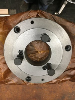
4B0743A1-9FD9-4015-B754-3843B9823712.jpeg
The problem I’m seeing is trying to align a hole to start.
My thought was center RT then part on RT. Move my distance from center to get hole location. But here’s where it would get goofy. Maybe block part in so that I can loosen part to spin. Then spin plate to align to existing hole. Note measurement. Go back to center of RT check d if moved then go back to measurement and see if it aligns. Then do the 120* and see where it lands. And then somehow time it if off???? Once I get the existing hole pattern aligned it’ll be a snap but getting there is the question.
Or go the simplest but not very precise way. Make transfer screw punches 3 of them and put in the 3 holes needing to be drilled. Then take three screws and put in existing holes to aligned plate to chuck and tighten a touch. The three transfer punches will give me the marks. Then just open up the existing holes and drill the others just off a punch mark on drill press??? Any suggestion would be greatly appreciated. Thanks.
 
Use your tooling. Center the RT. Center the backing plate on the RT. Use a machined diameter to find the center, internal or external. Fasten the back plate down solidly. Double check that the back plate is concentric with the RT. Offset the RT by the desired radius. Make holes, using the RT to set the spacing for the bolt circle.
 
Use your tooling. Center the RT. Center the backing plate on the RT. Use a machined diameter to find the center, internal or external. Fasten the back plate down solidly. Double check that the back plate is concentric with the RT. Offset the RT by the desired radius. Make holes, using the RT to set the spacing for the bolt circle.


So that’s what I was thinking but do I care if it’s not at zero when I align the existing first hole for the pattern? Just zero whatever number it lands on then start the hole pattern?
 
I have done that with transfer screws when I had a backplate with no holes at all, ones that I made myself. For transfer screws, I used pieces of allen capcrews with a small diameter teat machined in the center and cut a slot alongside the teat to screw them in and out with a screwdriver. I screwed them in so that just a tiny bit was above the machined face, set the backplate on and whacked the backplate with a lead hammer to make the center marks, then enlarged them with a regular center punch, then center drilled and drilled and counterbored for the screws. Why overly complicate a simple job?
 
So that’s what I was thinking but do I care if it’s not at zero when I align the existing first hole for the pattern? Just zero whatever number it lands on then start the hole pattern?
You may need to clear some of the existing holes on the back plate. You can start anywhere you want. If you want a three bolt pattern, just set the holes 120 degrees apart, starting anywhere you want to. Do the math on a piece of paper if you are using odd numbers on the RT, to keep from making math mistakes. Been there...:eek 2:

Edit: It pays to go around the pattern without cutting once to make very sure you will miss all existing holes.
 
It just the nature of the beast. I wanna do as you said but for sum reason I’m second guessing myself as I do. I know I can pop some holes in it and make it work. I figured their is a better, more precise way that guarantees hole location??
I think I will still do the transfer marks just to confirm but the problem I see is the hole will need to be drill from the d1-4 side to counterbore heads. Unless holes are drilled then flipped to counterbore heads. To me that’s a lot of guessing the bit will be center. And my luck is one screw will be off a quarter of a bolt hole or the counterbores won’t be centered to hole and bolt stops or get super tight at counterbore.
 
Yes I always right all my numbers down and have right there as reference. I will see what happens tonight if possible. Trying to avoid making Swiss cheese out of this thing. Thanks guys!
 
If I wanted to use the existing holes, I would center the RT on the table and center the backplate on the RT. Then I would move the table in x and rotate the RT table to center the mill on one of the existing holes. I would note the RT reading and machine the first hole. Then I would rotate 60º if making six holes or 120º if three and machine the second hole. Repeat the process for the remaining holes.

One caveat regarding Chinese backplates. Some of them have mounting holes that are not exactly positioned. I would measure the distance from hole to hole to verify the position. Since you are mating to your chuck, it should be your standard for hole positioning.
 
My problem is not laying it out or hole locations. The problem is aligning existing holes to the degrees on the RT. I would like to start at zero with the first existing hole. Then my numbers are easy 60-120-180 and so on. If that first hole lands 7*35 sec. then the math I guess not terrible but it would be nice to land on some degrees not degrees and seconds.
 
Back
Top