It depends really, since there are more ways to skin this cat. Once you use the software for a while, you will develop drawing habits to suit your style.
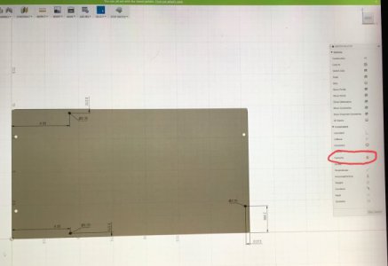
My go-to method is to just create a new sketch, label it "dimensioning", and drop points/centerpoints that I may need to grab. It is more work going back to do this, but in this case you could have drawn the same "pattern" in the sketch environment instead of using the solid features. This would have given you wireframe that could be utilized instead of a lifeless solid. I prefer this new sketch method because utilizing construction planes is very intuitive way to create the geometries I need very quickly.
Another easy way to get your dimensions is to go into the Drawing environment. You can get there the same way that you would jump from Modeling, Patch, Sheet Metal, Manufacturing, or use the File tab. Old habits have me using File, so I typically access from there.
File --> New Drawing (from design) --> specify units and preferences ---> click okay.
Just be sure to deselect "full assembly" and you will be able to isolate the component you want if there are multiple bodies in the file.
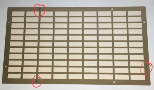
Drop down a base view in the orientation you want to grab dimensions from, and now you can dimension from any hole centerpoint to any edge. Lay down some GD&T if you want, and print for shop use.