Motors Minimum RPM ( wrt rigid tapping )

I believe the GS3 FB card can support a pretty high pulse rate from the motor encoder. My Hitachi VFD is limited in this regard, but the GS3 can take the quad inputs directly. And it looks from the specs that the Acorn can take the 2kPPR spindle encoder just fine.

Should work a treat. Just make sure to route the encoder wires well away from the motor power leads.

Will do, I'll route them as best I can... its like a spaghetti ball in that electronics box right now ! lol But I used some good double shielded wire and grounded it to the VFD only.. so hopefully it will be "ok". I'll report back if I notice a significant difference between my Delta VFD without tuning or encoder, and the DuraPulse with the Encoder feedback and properly auto tuned.

Cheers,

Jake
I read somewhere to twist the 3 VFD wires together before running them in the conduit to the motor - leaving the motor ground wire out of the twist. This mimics the swanky Belden VFD cables where the motor wires are molded in to a helix before adding the shielding and sheath. Belden, of course, uses 3 ground wires, plus shielding, plus other expensive magical tricks and top shelf materials.

I didn't want to pay a million dollars per foot for Belden cable, so I just did the twist thing and ran the conductors in separate metallic cable all the way to the motor. So far, no problems with noise.
 
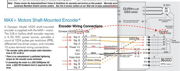
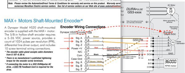
I'm getting an "encoder loss" error upon firing up my spindle motor with the encoder enabled in the VFD. I've double checked all the wires to the feedback card and determined they have continuity and match the enclosed diagram I made. My settings in the VFD are below. Also enclosed is the wiring diagram I used.

10.00 = 1024 ppr
10.01 Encoder type = Quadrature FWD - CCW
10.02 ( default ) proportional control = 1.0
10.03 ( default ) Integral Control = 1.0
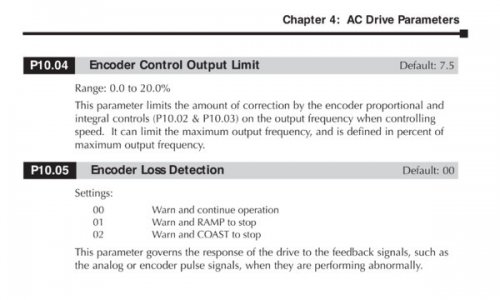
10.04 ( default ) Encoder Control output limit = 7.5%
10.05 ( default ) Encoder Loss Detection ) = 00 ( warn and continue )

The model # of the encoder is Dynapar H20 - HS2010248X4BX11

Here is the wiring diagram I used :Screen Shot 2018-02-04 at 6.21.00 PM.jpg
Jumpers set to 5v and Totem.

If anyone has any advice, I'd love to hear a solution, or at least some comforting words :)

edit : I spoke with the encoder manufacturer. I am supposed to verify across the common on the encoder that its getting roughly half the input voltage at A, B, A not and B not ( while slowly, I'm assuming , hand rotating the motor ). This would indicate whether the encoder itself is working properly.

Cheers,

Jake
Screen Shot 2018-02-04 at 6.21.00 PM.jpg
 
Last edited:
I've I'm reading the Dynapar tech sheet right, I think that model HS20 is an open collector output. HS2010248X4BX11 is the open collector; if it were HS2010248X4BX21 then it'd be a push-pull (Totem).

Try changing the jumper on GS3-FB.
 
I've I'm reading the Dynapar tech sheet right, I think that model HS20 is an open collector output. HS2010248X4BX11 is the open collector; if it were HS2010248X4BX21 then it'd be a push-pull (Totem).

Try changing the jumper on GS3-FB.

Thanks Spumco! Sadly, the above wiring diagram that I posted previously for the Feedback card was an "artist" rendering... closely mimicking the general look and orientation of the card itself but the terminal order was drawn with "artistic license" to my chagrin. After rewiring using the diagram from the manual itself ( see below ) ... I am no longer seeing the "encoder loss" fault. I haven't put it through its paces much, but all appears ok. This is in the totem setting. I tried the OC setting but it wouldn't have changed anything. In the future I could add some required resistors and try it in Open Collector mode but for now, I'm going to enjoy the fact it appears to be working and move on for the time being

For anyone doing the same, here is the proper diagram for the GS3-FB card. Messages Image(501127318).jpeg

Cheers,

Jake
 
Well done you.

I hate 'sub-optimal' tech literature.

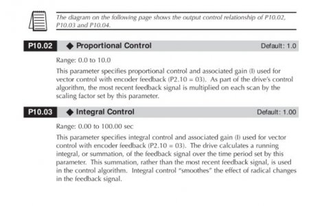
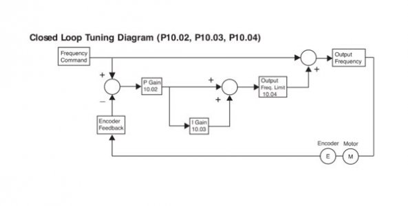
Ok, so now that I know the wiring is correct and I'm no longer seeing an encoder loss error, however my success is short lived. After using the mill the first time it appeared all was ok, but on subsequent sessions I've experienced "cogging" / jitter ? The spindle seems to knock and sputter and actually won't spin sometimes from either a stop or upon changing speeds ( M3 S600 to S1000 ). The solution is to turn off Encoder control, then all works fine. Again, note, though all this, I don't see the Encoder Loss anymore at all....So, I'm assuming I need to tweak the parameters specified in the manual ( see enclosed picture ). I'm hoping someone can give me some insight on the proportional ( 10.02 ) integral (10.03) and (10.04) Encoder Control Output limit settings. In talking with my brother we both believe it is more likely a parameter that needs "messaging". Not seeing the "encoder loss" error even when the motor is sputtering and knocking, is a good clue to this assumption.

I'm reluctant to use "blind" trial and error due to the significant harm this could cause the motor, so if anyone has ANY experience with these settings , I'd sure appreciate any thoughts on where to start with these adjustments. It surely will be better than me just throwing darts, so to speak.

Jake

from the Dura Pulse GS3 manual :
Screen Shot 2018-02-19 at 11.09.40 PM.jpgScreen Shot 2018-02-19 at 11.09.52 PM.jpgScreen Shot 2018-02-19 at 11.09.59 PM.jpg
 
Last edited:
It sounds like your Acorn and GS3 are having a battle for control of the motor. If you have encoder feedback from the motor going to both then each may be trying to control the speed.

Did you run the Auto Tune function after installing the encoder? Is your Accel/Decel set lower than the system capability?

The Proportional Gain sets the ''stiffness'' of the system. Too high = unstable system, too low = ''mushy'' response.

The Integral Gain sets the rate of change based on the error. Setting lower normally helps smooth things out.

I don't think you will hurt the motor by incorrect settings, but it can get a little scary if the system goes unstable.

If you don't get this worked out pretty quickly, I'll be doing the same thing with a GS3 in the next few days so I will have a good understanding of how to do it and will be able to offer some personal experience.

Hi Jim,

thanks for your reply, and I look forward to what you find out with your GS3 in the coming days.

I was able to disable the Acorn's spindle encoder and verify that the problem continues, so it isn't a tug of war between the two encoders.

I believe the auto tune only sets the resistance of the motor and also the unloaded Amp rate. This info was from a previous call to the VFD manufacturer / tech.

I was able to make this issue go away by using your descriptions of the proportional and integral gain settings as a guide. I halved the values from he defaults and the bad behavior went away. I also, initially just set the 10.04 setting to 3% and the issue went away too but increased it back to the default before I halved the other settings. So its clearly just needing some fine tuning and further testing. Oh, and previously I set the acceleration rates high ( less aggressive ) values, and the issue did not go away. So it all has to do with the aggressiveness of the gain with regard to the "error control" of the encoder. Its still quite possible that the wires need to be routed better as Spumco suggested previously. ok, off to the dentist! lol

Best Regards,
Jake
 
Back
Top