Bruce,
Now that I've dug a little deeper into the head, I'm starting to see the exploded parts diagram more clearly. I count 3 bearings on the spindle, MV-907 is a bearing at the top of the spindle inside the quill, and 2x of MV-9011 bearings down at the bottom of the spindle, inside the quill. I'm curious if the two bearings you show are the two types and which one I need two of. I'm also completely lost as to what part numbers MV-905 and MV-9012 are...? They seem to be spacers between the two MV-9011 bearings at the bottom of the spindle. Also, MV-9017 is the C/R 275127-M1 seal that I have showing up tonight. Do you know what any of those spindle bearing parts are?
In happy news, those bearings are available from Timken still, even though they're old Fafnir part numbers, and not terribly expensive from either Motion Industries or Amazon.
Thanks,
Will


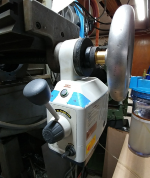
") Thanks go to you Will, this is more info and activity on the Hedwick than I have seen since I got my mill in 1996. I have the tachometer on mine, I will need to pull the cover off so see what is printed on the back of the unit. I just got mine installed last spring. It was missing the drive wheel and o-ring. I took a wag at the size and machined one up. The shaft was sticky with dried lube, after oiling the shaft it loosened up enough to run but the needle does not return to 0. It sits at about 250 rpm.
Thanks go to you Will, this is more info and activity on the Hedwick than I have seen since I got my mill in 1996. I have the tachometer on mine, I will need to pull the cover off so see what is printed on the back of the unit. I just got mine installed last spring. It was missing the drive wheel and o-ring. I took a wag at the size and machined one up. The shaft was sticky with dried lube, after oiling the shaft it loosened up enough to run but the needle does not return to 0. It sits at about 250 rpm.