Rotary Phase Converter Rebuild / Build

That sounds pretty good. Nice job !
Thanks Jim,
The idler has an open frame with an internal fan so I think it's as quiet as it'll get.
Just saw a 10 hp tefc for $100 on CL, getting in car now...
 
New Problem.
The 10 hp motor I went to look at appeared to have a bad bearing(s) and the guy wouldn't knock anything off the price so I passed on it. I know bearings aren't hard to change but I don't need more projects now and 10 hp was really more than I need anyway. Besides, He did have a smooth turning 7.5 hp available. I tested it out as best I could: Each winding to motor housing, no continuity. Between each winding, .5 ohms Apparently, no opens and no shorts so I bought it.

However, when I hooked it up to the phase converter, in place of the original idler, it won't get up to speed. It just turns slow, about a hundred rpm then trips the breaker (30 Amp) after about 20 seconds. I did try adding some more caps on the start circuit but still was a little shy of the estimated 562.5 µf. (@75 µf per hp) Could it be a bad motor or do I simply need more start-cap farads?
 
That's odd. Maybe a trip to the motor shop would be in order.
 
Update: I got the new idler motor running, its fine. First I tested it by hooking up the old idler back up, I put a manual starter switch on the new idler motor and connected it to the bus. I started the system with the old idler then fired up the lathe motor and then kicked in the new idler, she started right up and purred like a kitten.
I surmised it was indeed a case microfarad deficiency of the start cap... So then I disconnected the old idler, hooked the new idler back in and connected all my remaining run caps in parallel with the start cap, that gave me over the recommended value. Hit the start and It worked, the new idler now starts on its own.
It was totally worth the effort, as the new idler runs much smoother an quieter then old one even after it was balanced. The lathe motor now runs smoother an quieter as well!

New start capacitor on its way from McMaster...
 
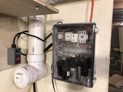
The additional start cap arrived and I pretty much wrapped up the project. Only a few minor details remain.
eBlA+WHEQeOhQp7e4hu62w.jpg
I mounted the start-stop switch next to the cabinet until I figure the best location. I could even have one by each machine.
Iyd52x4tTGiI2HA0cQczEw.jpg
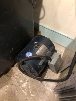
I mounted the idler motor on a pair of hardwood skids and set it on a piece of rubber sound attenuation matting. I'll also make a cover for exposed shaft. I milled out the back of a 5" junction box and mounted it to the terminal box that was missing it's cover.
Viskvn3BT5akP1MfLmqHwA.jpg
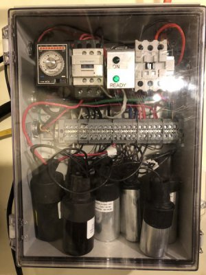
Next time I get in there, I'll shorten & neaten up the cap wires and make a retaining strap to keep them in place when opening the cabinet.
WM+bXl%VQwWzjfqM4ZmADA.jpg
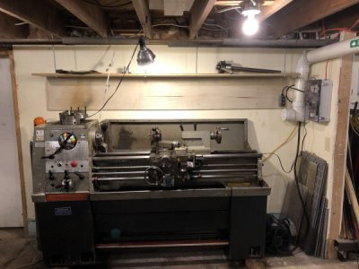
Eventually, I'll place the idler under the lathe, where there's plenty of dead space.
RPC 4.jpeg
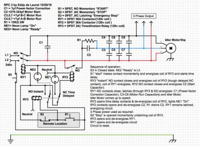
The final schematic, pretty much as built. I didn't mount S3 (E-stop) for now as the Start-Stop switch is right next to the cabinet.
RPC values .jpeg
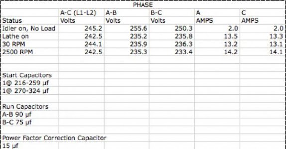
This is how it balanced out, I'm very happy with the results. I wasn't able to measure the current on phase B (the generated phase) as I couldn't pull out enough wire to get the ammeter on it, perhaps next time... But it probably isn't necessary as the system runs smooth and quiet, which is what I was after.
Now it's back to Craigslist with the George Snyder unit...


Last edited:
Back
Top