

-
Welcome back Guest! Did you know you can mentor other members here at H-M? If not, please check out our Relaunch of Hobby Machinist Mentoring Program!
You are using an out of date browser. It may not display this or other websites correctly.
You should upgrade or use an alternative browser.
You should upgrade or use an alternative browser.
11 x 26 Conversion With Centroid Acorn control and closed loop steppers
- Thread starter jumps4
- Start date

- Joined
- Apr 30, 2012
- Messages
- 2,401
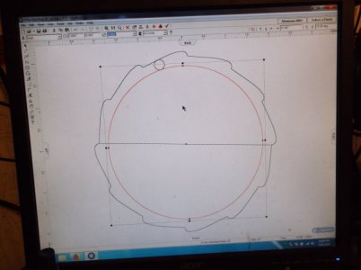
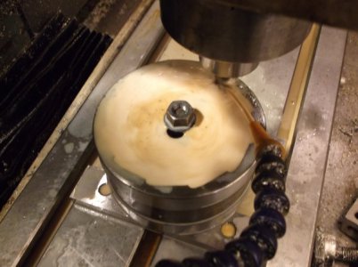
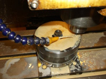
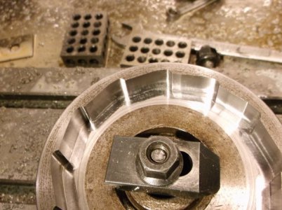
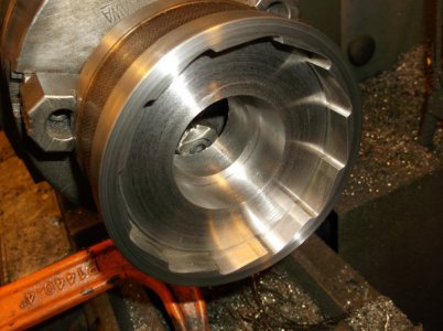
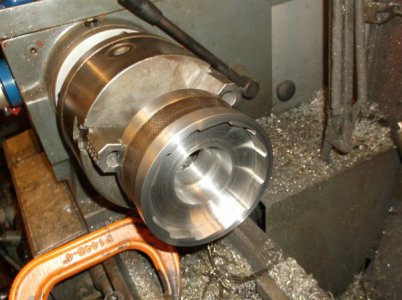
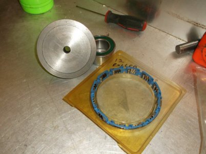
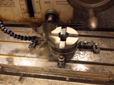
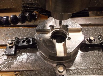
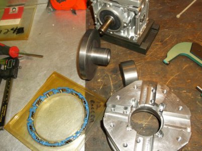
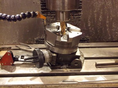
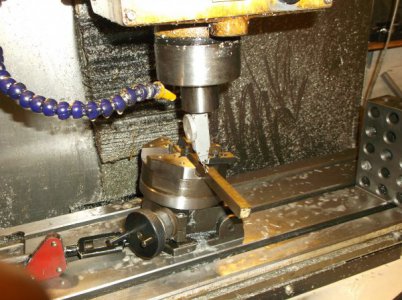
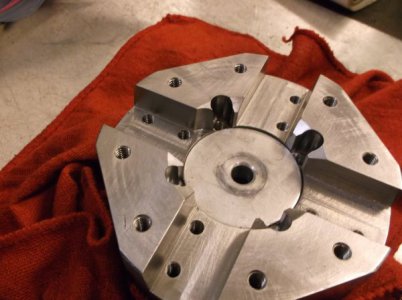
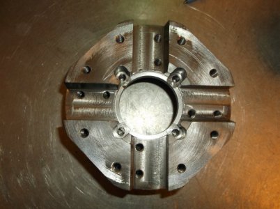
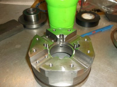
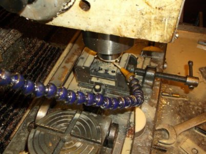
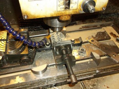
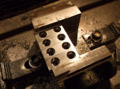
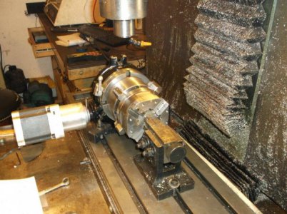
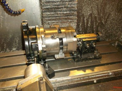
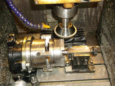
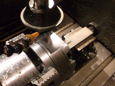
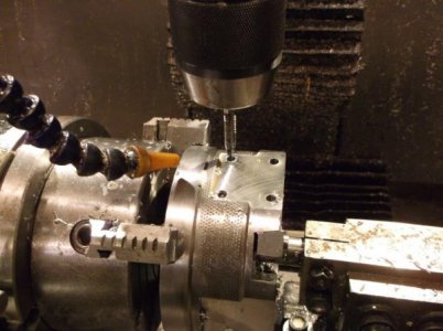
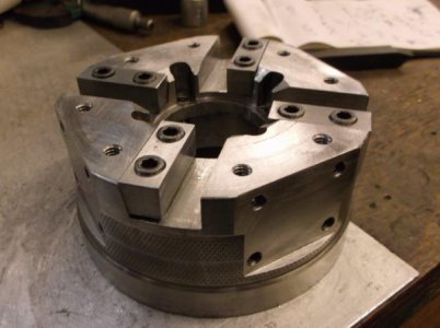
I have started building an Automatic Tool Turret for the lathe.
I'm using a one way sprag roller clutch for the brake when force is on the cutter and a 30 to 1 Nema 23 worm drive.
The drive will be 8 position.
I'm using a one way sprag roller clutch for the brake when force is on the cutter and a 30 to 1 Nema 23 worm drive.
The drive will be 8 position.
Attachments
-
 DSCF2433.JPG57.3 KB · Views: 27
 -
 DSCF2434.JPG67.1 KB · Views: 27
 -
 DSCF2435.JPG46.6 KB · Views: 21
 -
 DSCF2436.JPG47 KB · Views: 20
 -
 DSCF2437.JPG31 KB · Views: 18
 -
 DSCF2438.JPG45.6 KB · Views: 15
 -
 DSCF2439.JPG49.7 KB · Views: 14
 -
 DSCF2440.JPG58.4 KB · Views: 14
 -
 DSCF2441.JPG37.9 KB · Views: 15
 -
 DSCF2442.JPG47.7 KB · Views: 15
 -
 DSCF2443.JPG30 KB · Views: 16
 -
 DSCF2444.JPG49.7 KB · Views: 16
 -
 DSCF2445.JPG53.9 KB · Views: 15
 -
 DSCF2446.JPG58.1 KB · Views: 16
 -
 DSCF2495.JPG79 KB · Views: 16
 -
 DSCF2496.JPG75.7 KB · Views: 16
 -
 DSCF2497.JPG47.7 KB · Views: 14
 -
 DSCF2498.JPG61.5 KB · Views: 14
 -
 DSCF2499.JPG77.5 KB · Views: 14
 -
 DSCF2502.JPG66.8 KB · Views: 14
 -
 DSCF2503.JPG68.6 KB · Views: 14
 -
 DSCF2506.JPG63.5 KB · Views: 16
 -
 DSCF2507.JPG61.9 KB · Views: 16
 -
 DSCF2508.JPG74.3 KB · Views: 16
 -
 DSCF2509.JPG76.4 KB · Views: 15
 -
 DSCF2510.JPG43.7 KB · Views: 19
- Joined
- Apr 30, 2012
- Messages
- 2,401
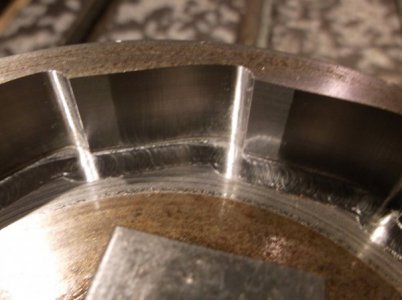
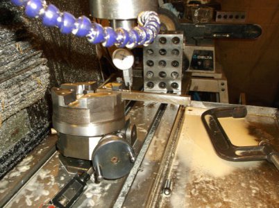
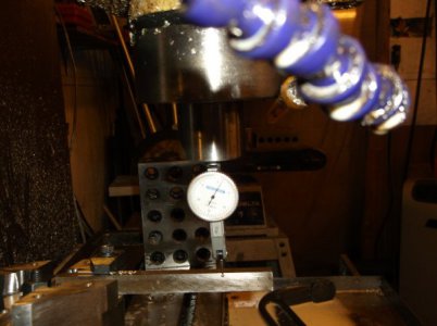
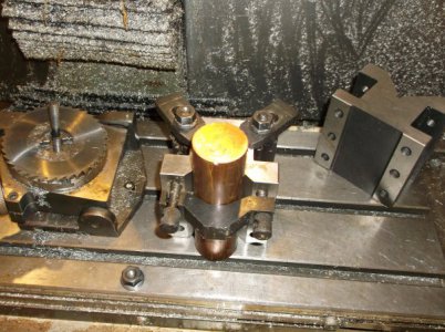
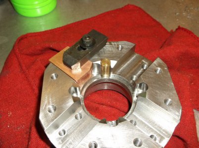
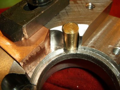
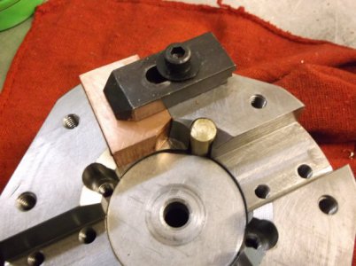
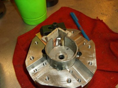
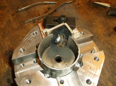
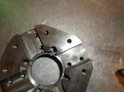
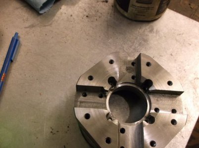
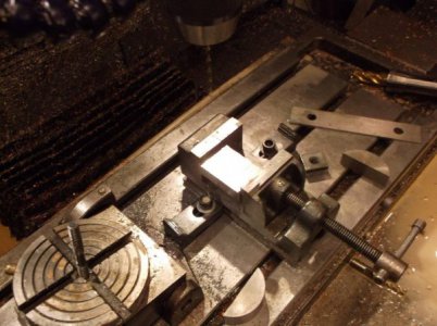
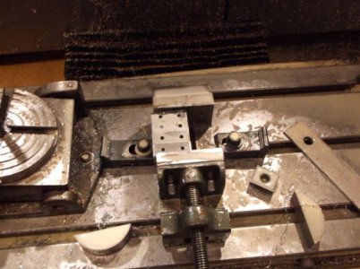
As usual everything was going to well and I'm not sharp enough to stop when tired...
I was cutting the taper for the tool locks and wanted to move over to position "-.120" but I typed "-120" and pressed enter before reading my typing.
So the next photos are repairing the damage I caused by not reading.
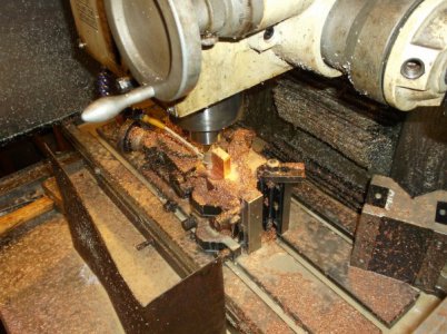
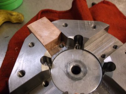
All fixed now but I had to make a few fixtures to keep from causing more damage while filling in the damage with weld.
the copper and brass parts keep the weld in the area I need it without causing me to re-machine everything in the area.
Thanks For Viewing
Steve
I was cutting the taper for the tool locks and wanted to move over to position "-.120" but I typed "-120" and pressed enter before reading my typing.
So the next photos are repairing the damage I caused by not reading.
All fixed now but I had to make a few fixtures to keep from causing more damage while filling in the damage with weld.
the copper and brass parts keep the weld in the area I need it without causing me to re-machine everything in the area.
Thanks For Viewing
Steve
Attachments
-
 DSCF2511.JPG48.3 KB · Views: 19
 -
 DSCF2512.JPG50.1 KB · Views: 18
 -
 DSCF2513.JPG47.8 KB · Views: 19
 -
 DSCF2514.JPG80.3 KB · Views: 19
 -
 DSCF2515.JPG78.3 KB · Views: 19
 -
 DSCF2516.JPG41.3 KB · Views: 19
 -
 DSCF2517.JPG60.5 KB · Views: 19
 -
 DSCF2518.JPG53.3 KB · Views: 19
 -
 DSCF2519.JPG49.8 KB · Views: 18
 -
 DSCF2520.JPG49.7 KB · Views: 18
 -
 DSCF2521.JPG60.8 KB · Views: 19
 -
 DSCF2522.JPG47.6 KB · Views: 18
 -
 DSCF2523.JPG44.7 KB · Views: 19
 -
 DSCF2524.JPG51.3 KB · Views: 19
 -
 DSCF2525.JPG51.9 KB · Views: 18
 -
 DSCF2526.JPG44.9 KB · Views: 25


- Joined
- Apr 30, 2012
- Messages
- 2,401
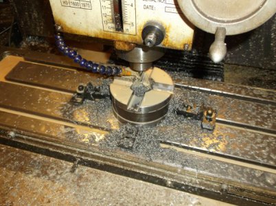
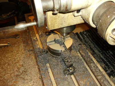
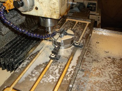
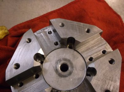
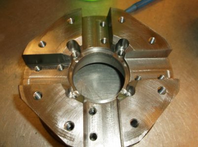
I made some more progress today.
I ground, drilled and tapped the side tool mounts.
I finished the tapered tool locks for the front tools.
Thanks for looking
Steve
I ground, drilled and tapped the side tool mounts.
I finished the tapered tool locks for the front tools.
Thanks for looking
Steve
Attachments
-
 DSCF2527.jpg64.2 KB · Views: 15
 -
 DSCF2528.jpg61.2 KB · Views: 15
 -
 DSCF2529.jpg69.5 KB · Views: 15
 -
 DSCF2531.jpg73.8 KB · Views: 15
 -
 DSCF2536.jpg49 KB · Views: 16
 -
 DSCF2535.jpg51.3 KB · Views: 16
 -
 DSCF2532.jpg58.2 KB · Views: 16
 -
 DSCF2537.jpg80.4 KB · Views: 16
 -
 DSCF2538.jpg75.4 KB · Views: 17
 -
 DSCF2540.jpg78.1 KB · Views: 16
 -
 DSCF2542.jpg49.9 KB · Views: 14
 -
 DSCF2543.jpg53.6 KB · Views: 14
 -
 DSCF2545.jpg44.5 KB · Views: 14


- Joined
- Apr 30, 2012
- Messages
- 2,401
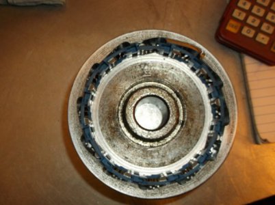
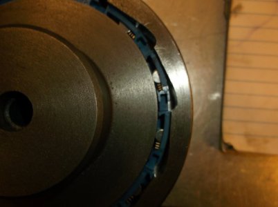
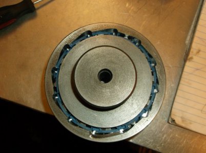
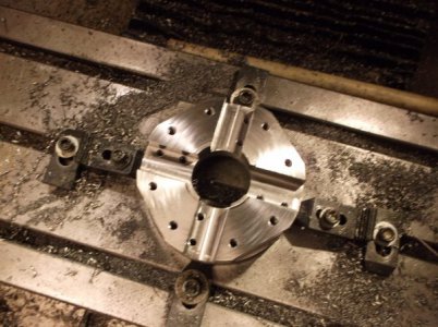
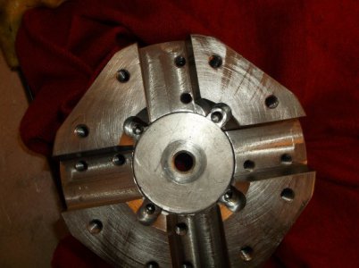
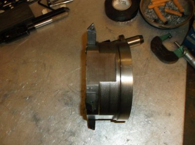
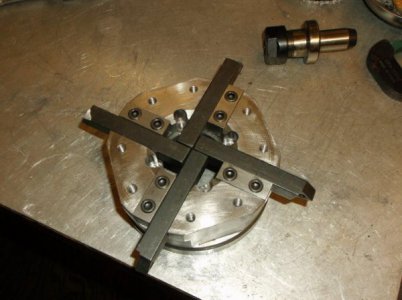
Today I designed and built the drive coupling.
The shaft has a straight spring wire through it that locks if turned clock wise and loads spring tension in the direction of cutting force
down on the tool. This takes the load off the worm gears and loads all the force on the sprag clutch.
All tool changes are in a clock wise direction and 45 degrees each. When the correct tool number is reached the direction reverses
2 degrees. The reverse direction does not rotate the tool it loads the spring in the drive coupling locking everything tight.
Now that it is finished I have to learn how to program the tool changes and I have no idea how to to do that yet...
Building it may have been the easy part!
I'll ask for help on the Centroid Forum
Thanks for viewing
Steve