- Joined
- Jun 8, 2016
- Messages
- 603
Long story, but here goes. My Logan is a factory turret lathe with dual toolpost cross slide. I bought it used of course, and the previous owner had made an adapter plate to put a Southbend 9" compound on the cross slide, eliminating the dual tool post. This is the condition I got it in:
![20170925_185604[1].jpg](https://www.hobby-machinist.com/data/attachments/277/277395-4409f1f03993a48c269b39d4ecfc83f4.jpg "20170925_185604[1].jpg")
Interesting to me at least is that this lathe has not only a forward and reverse switch, but also a 2 speed motor with high/low speed switch located between the on off and speed adjustment wheel. I havent seen that on any other Logan machine, and would love more info on it. But that's another topic.
Previous owner had used a shop made adapter plate to mount the compound and then had what appeared to be a shop made quick change tool post:


Pretty quickly I purchased an AXA wedge type QCTP and tool holders and am very happy with that decision. The problem is that I have no way of reading the compound angle. The compound could be adjusted but it was very 'floppy' and the adapter plate itself would move in multiple directions. It took me a while to realize this was actually a compound from a small Southbend lathe. You can see the adapter plate here:


One other issue I have with this is that somehow the compound will "rock" ever so slightly under heavy cuts. I had my eye on a standard cross slide but let it pass due to not really knowing what I needed. So, I had to make an adapter of my own.
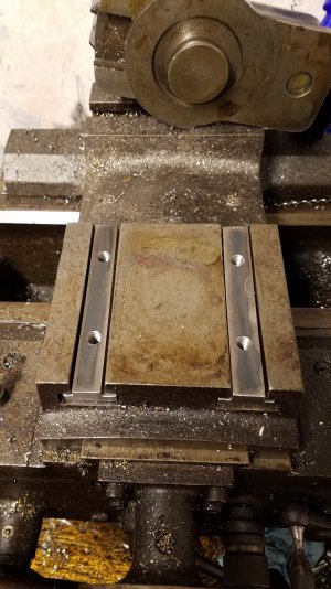
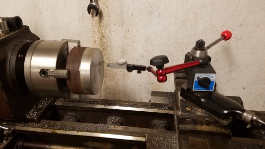
I first made a pair of T-nuts to fit the cross slide:

I made them long enough to fit the entire slot. I bought a piece of steel plate, I think it was 1018 and milled it to fit the top of the operator-side t-slots so I could cover the entire area. I used my mill to true it up. I'm not sure what the best way to do that is, but here's what I did. I mounted the plate on the vice (moved the jaws to the outboard ends), and used a fly cutter to flatten the top. With out breaking it down, I swapped to an end mill and trued the 2 exposed sides or ends to size. In my mind the top and the 2 sides were then flat and 90 true to each other. Then I flipped the piece and rotated 90* and repeated the procedure, fly cutter and end mill. At that point I believe to and bottom are parallel and 4 sides are perpendicular. Then it was just a matter of measuring and drilling 4 holes to fit the T-nuts, and drilling and tapping the T-nuts to match. I drilled the plate for 5/16 bolts and counter bored for the bolt heads and clearance for a socket to fit.
Interesting to me at least is that this lathe has not only a forward and reverse switch, but also a 2 speed motor with high/low speed switch located between the on off and speed adjustment wheel. I havent seen that on any other Logan machine, and would love more info on it. But that's another topic.
Previous owner had used a shop made adapter plate to mount the compound and then had what appeared to be a shop made quick change tool post:
Pretty quickly I purchased an AXA wedge type QCTP and tool holders and am very happy with that decision. The problem is that I have no way of reading the compound angle. The compound could be adjusted but it was very 'floppy' and the adapter plate itself would move in multiple directions. It took me a while to realize this was actually a compound from a small Southbend lathe. You can see the adapter plate here:
One other issue I have with this is that somehow the compound will "rock" ever so slightly under heavy cuts. I had my eye on a standard cross slide but let it pass due to not really knowing what I needed. So, I had to make an adapter of my own.
I first made a pair of T-nuts to fit the cross slide:
I made them long enough to fit the entire slot. I bought a piece of steel plate, I think it was 1018 and milled it to fit the top of the operator-side t-slots so I could cover the entire area. I used my mill to true it up. I'm not sure what the best way to do that is, but here's what I did. I mounted the plate on the vice (moved the jaws to the outboard ends), and used a fly cutter to flatten the top. With out breaking it down, I swapped to an end mill and trued the 2 exposed sides or ends to size. In my mind the top and the 2 sides were then flat and 90 true to each other. Then I flipped the piece and rotated 90* and repeated the procedure, fly cutter and end mill. At that point I believe to and bottom are parallel and 4 sides are perpendicular. Then it was just a matter of measuring and drilling 4 holes to fit the T-nuts, and drilling and tapping the T-nuts to match. I drilled the plate for 5/16 bolts and counter bored for the bolt heads and clearance for a socket to fit.