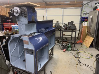
1964 10EE lathe

rabler

Addlepated tinkerer
H-M Lifetime Diamond Member
Joined
Feb 25, 2021
Messages
3,115
The CK I posted about in another thread is a great lathe, certainly sturdy. But it is not the machine for spinning anything over 1000rpm. I'd been working with a 10x22 import lathe and realized a spindle speed faster than 1000 is certainly useful for carbide on small diameters. And I decided I really like fixing up the older machines. About a year ago I ran across a Monarch 10EE for sale in Wisconsin. Pretty rough shape, but running. 5HP DC motor, that had been modified with an after market "Danfuss" controller that wouldn't run the spindle up over 1000rpm.

DC motors are a bit strange in that there is both an armature and field, basically a rotating electromagnet and a fixed electromagnet. The rotating electromagnet (armature) gets driven through brushes that activate the appropriate orientation to push against the fixed magnet (field). To vary speed in this type of DC motor the voltage to the armature is increased from zero to maximum, and then to go faster, the current to the field is decreased. (Sorry to any power/motor experts if I'm butchering this). That requires a fairly complicated set of controls feeding the DC motor. Monarch went through quite a bit of variation in doing this over the 4+ decades that the 10EE was mass-produced, and the control electronics have always been the Achilles heel of these lathes.

Anyhow, this lathe was meant to spin up to 4000rpm on the spindle, but the existing controller would only get up to about 1000 rpm.
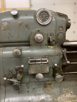
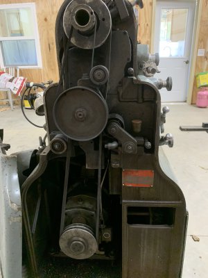
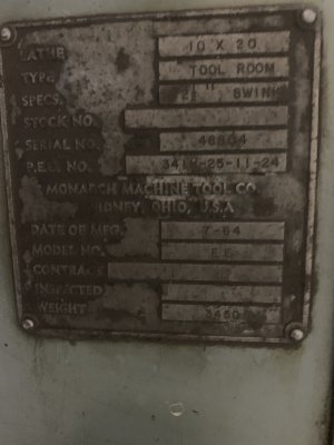
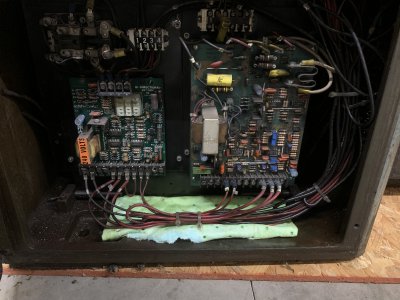
IMG_3093.JPGIMG_3095.JPGIMG_3094.JPGIMG_3096.JPGIMG_3105.JPG

I'll add more to this thread soon ...
 
I did quite a bit of reading om practical machinist on fixing the DC mechanism in these. Two possible routes became obvious, basically replacing the DC controller, or replacing the DC motor with an induction (standard AC) motor and vfd.

The monarch 10EE is a bit unusual for a lathe in that the spindle is ungeared. It is a straight through shaft and however fast the belt drive turns that end is how fast the chuck or whatever is mounted on the working end will turn. And yet you get this incredible range of useable speed, like 10 rpm to 4000 rpm on mine. This is done via a DC motor which has torque over a fairly broad range of rpm, plus a reduction gear mounted on the motor, giving direct motor rpm out, or IIRC a 5:1 reduction.

The challenge with the induction motor plus vfd route is even with a good vfd, 10-4000 rpm on the spindle is a 400:1 range of rpm to operate. Many vfd machines we see today run 20-2000 rpm, 100:1, by using two or three geared speed ranges. Also, a vfd driven motor roughly creates the same torque at speeds less than the design speed of the motor. HP = rpm * torque * constant, where constant is a number which depends on units used. So if torque is constant, than as rpm drops, so does HP. On a lathe if you are looking for a certain SFPM cutting speed, you go slower on bigger (larger diameter) parts. Larger diameter means less leverage for the motor, so the motor needs more torque to give the same force at the cutting tool at that SFPM. So a VFD isn’t to optimum configuration for getting power to a machining tool as we reduce rpm below the motors rated speed. On the other end, as we increase rpm above the motor’s rated speed, vfd’s have to reduce the torque as speed increases (above the 60Hz speed of the motor), to keep the motor from exceeding its rated HP output. This matches well with what we want for most machining. Turning faster is associated with smaller endmills or smaller diameter workpieces in the lathe.

One takeaway from this is if you have a vfd machine with multiple speed ranges and you need the most cutting power, you should opt for the lowest speed range that will give you the desired cutting speed. So if your lathe has ranges 50-500 and 200 to 2000, and 400 rpm is your desired cutting speed, you are better off using the 50-500 rpm range. The high range will of course still give you the option of 400 rpm, but less cutting power. Just like you can use third gear at 20mph in your manual transmission car, but if you want to accelerat, downshift to 2nd or first.

Ok, rhe point of all that explanation is that a VFD driven motor isn’t going to give you good cutting performance over a spindle rpm range of 10-4000 rpm. There are two ways to help this along. One is to use some gearing. The other is to use an oversize motor.

The 10EE does have that reduction gear in its design. The challenge is that the reduction gear is part of the DC motor assembly, between the DC motor and the drive pulley. So you can’t just take the pulley off and put it onto a VFD driven motor without losing the reduction gear. Quite a few 10EEs out there have been converted in just that way, the reduction gear is discarded along with the old motor. Even with a ridiculously oversized motor (commonly up to 10HP) the low rpm performance suffers. Singke point threading is one area that this can become an issue. Since that is one area where the classic 10EE shines, it is a shame to sacrifice capabilities in that area.

A very good solution to this is to re-use the original reduction gear unit. This is somewhat complicated to do in that the original DC motor is not a simple keyed shaft but rather a splined shaft into the reduction gear. This has been solved many ways, such as making a keyed shaft to spline adapter, or more commonly just cutting off the spline end of the original DC motor and putting a keyway on the cut end, along with a coupling.

So, a large (5-10HP) AC induction motor, reduction gear adapter and VFD is probably the cleanest solution. That’s not necessarily cheap, unless you can find a bargain on a good used AC motor and suitable VFD.

The option I took was to preserve the whole motor assembly and build a new DC motor control system. In retrospect that certainly wasn’t the quickest solution to a functional lathe, and is only practical in that I do have a background that includes electronics. I also wanted to run the whole thing off single phase rather than a phase converter.
 
Last edited:
That OP summarized considerable research into a few paragraphs. It should help many readers understand the trade-offs. Thanks for posting.
 
Instead going the VFD and AC motor route, I decided to try building a new DC motor controller. I wouldn't really recommend this approach, but there are some reasons that Monarch used a DC motor in these things. Two primary reasons are: DC motors can cover a wide RPM range, and DC motors have a lot of low speed torque. Drill/drivers of the cordless or even of the older corded era are a good example. Spin fairly fast, and under load the slow down but can develop a lot of torque to turn in a screw or turn a large drill bit. Starter motors on your car are also DC motors, again low end torque, but there your battery is also DC so that makes it an easy match.

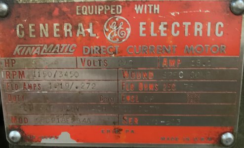
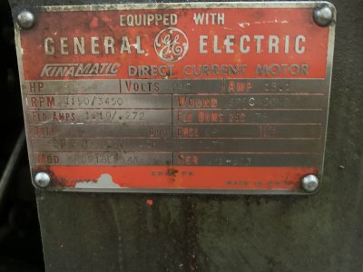
My 10EE came with a 5 HP DC motor. Here is a copy of the data plate,cropped a bit closer than the above picture:
IMG_3094c.jpg
Volts: 240,
Amps: 18.1
RPM: 1150/3450
Fld Amps 1.19/.272
SEP EXC 120V MACH TOOL DUTY

This means it wants 240VDC on the armature, at 18.1 Amps, to achieve 1150 RPM. At 1150 RPM, the field needs 1.19 amps at 120V. To achieve 3450RPM, we need to REDUCE the field current to 0.272 amps.
To get less than 1150RPM it'll need to be fed a voltage less than 240VDC on the armature.

So basically this thing needs two variable output DC power supplies. One for the field and one for the armature.
Converting AC to DC is why these things get complicated. Monarch went through a lot of variations in making this work. Some of the earliest 10EE's used an AC motor to turn a DC generator to run the DC motor. They went through a couple generations electronic approaches, mostly using old fashion vacuum tubes. I'm sure those of us over a certain age can remember when every hardware store had a tube tester and stocked a few vacuum tubes, but those have gone the way of 8-track tapes. Or is that cassette and VCR tapes?

240VDC is not straightforward to generate from your 240V single phase AC circuit. While theoretically 240VAC is actually the RMS (root mean square) voltage and the AC line sinusoid actually peaks out at 240 * sqrt(2), roughly 340 volts, RMS voltage is used so that RMS voltage * RMS amperage = average power. (AC current is also measured RMS). Volt meters and current meters are calibrated in RMS volts or amps. Anyway, converting AC to DC isn't perfect so typically you can't get 240VDC out of 240VAC for a high powered circuit. (Remember we need 18.1 amps). All we need is 20 car batteries in series, right?

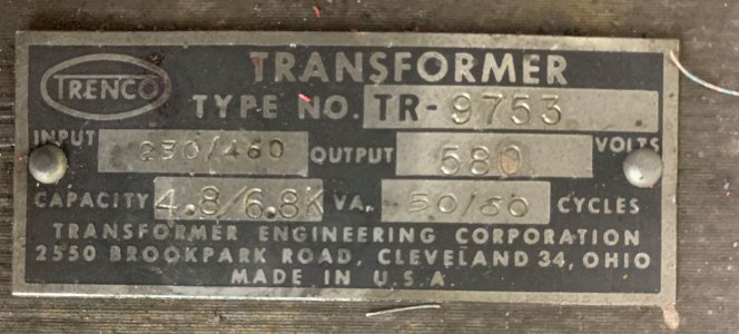
Why didn't they use a DC motor with a smaller voltage requirement? You can build a 5HP motor that uses less than 240V, but the trade off is the motor gets bigger. So obviously they were trying to keep the motor to a size to fit in the base. To get the enough DC voltage, the easiest solution was to use a transformer to raise the AC voltage up higher than 240V. (Transformers don't work for DC). Monarch used at huge 6.8KVA transformer to boost the AC voltage up to 580 volts AC (that is not a typo).
IMG_3388c.jpg


I'd guess that transformer weighs at least 100lbs. I have it on my bench. Unfortunately the leads on it are corroded beyond usable. So it makes a good doorstop I guess.

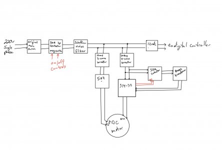
I did some reading and searching, and found a few people had successfully used Parker/Eurotherm DC controllers, namely a 514-32 and a 506 or 507 as the two DC power supply controllers for 10EEs using single phase 220V. Here is the basic power circuitry schematic I came up with for using those for the motor in my 10EE (note that there are several different DC motor options, 3HP DC was more common than 5HP).
pwerschematic.jpg
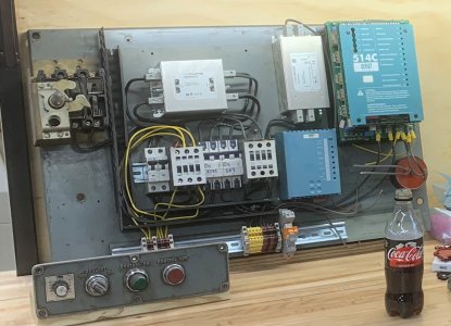
The "boost transformer" on the far right is the replacement for the above Monarch original. The Parker 514 is a solid state unit and a bit more efficient than the older tube electronics so I only need around 340VAC into the 514 to get full rated power out of the existing DC motor. Her's what that schematic looks like in implementation:

power supply.jpg

This is the panel that lives under the lathe bed behind a door on the front lower right of the lathe. The top left contraption is a 3 pole (3 phase) switch that protrudes through the door and has a large on/off handle. That switch is the only original equipment on that panel. The smaller panel in the lower left has the original on, off, and coolant switches. Note that the original panel had a nice easy to press protruding "On" switch, while the Off switch is recessed. Obviously modern safety standards have changed.

The blue boxes on the right side are the two Parker DC controllers, purchased used off of Ebay. The 514 was not cheap, $400+ used. (Did I mention that the VFD route made a lot of sense as long as the reduction gear was retained?) Obviously this panel doesn't include the DC motor itself, nor does it include the boost transformer. (Actually the motor can be spun up without the boost transformer, just doesn't deliver full power).

This doesn't cover a completely working setup yet. The 507 and 514 need some control inputs that tell it what voltage and current to deliver to the motor to give the desired RPM.
 
Last edited:
DC motors are a bit weird. As I mentioned above the field current is reduced to increase RPM. Taking that to the extreme, once spinning, some DC motors will actually spin up to self destruction if the field current goes to zero. So, if the smaller 507 field controller fails for some reason, the 514 needs to be shut down immediately to prevent this type of runaway motor. I've been told by one person that they tested this on one of the 3HP Monarch supplied motors and that it max'ed out before self destructing. Not going to test that myself.

Further, to control this we're controlling two DC power supplies, the Parker 514 and the 507. The approach I've heard used is to use a separate potentiometer for each one, along with a few relays to be sure they power up/down together. You then dial in the both to get the RPM you want. Basically you need to understand how to set both power supplies to get a desired RPM. I really didn't like the sound of this approach. Especially as reversing the spindle is then also controlled by one of those pots. Just too much to think about while trying to go forward/backwards for say, threading.

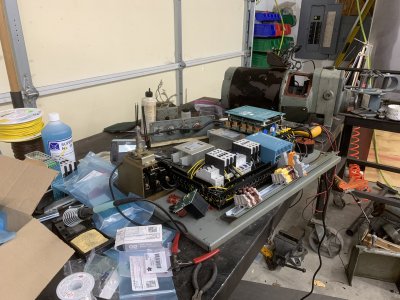
So here is where I went overboard. I decided to build a microcontroller circuit to manage all of this. I had the guts of my 10EE spread out on my welding table, electronics, plus all the mechanical bits of the apron, carriage, gearbox, etc.
IMG_3370.JPG
IMG_3392.JPG


To start with, that meant I needed an electronics bench in my shop. I had some maple flooring left over from a previous house, so I ripped the tongue and groove off of those and glued up a nice heavy maple bench. Weldeded up a frame, added a upper shelf for measurement instruments, and a plywood back.
IMG_3416[1].JPG
IMG_3421[1].JPG

Add some bins for parts, put the oscilloscope, bench power supply, soldering iron on there, and my shop now has a very useful electronics station, instead of my usual worktable being tied up with electronics work as it was when I first started the electronics side of this. I like to be able to hop between parts of a project or different projects so this was critical for me.
IMG_3428[1].JPG
 
Last edited:
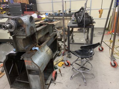
If you look at the first picture in my previous post, you can see that the lathe is pretty dirty. These 10EE's have all sorts of cavities in the base. I really wanted to clean it up, but getting down on my knees on a concrete floor wasn't appealing. I wanted a height that I could sit on a stool or 5 gallon pail while scrubbing and painting. So I fabbed up a stand complete with wheels to lift the whole thing up about 16". You can see here I've also done some work on cleaning and painting. I used the lighter blue for interior surfaces, so anything in the light blue/gray eventually get covered up. But it makes those compartments a little brighter and easier to see into, helpful for finding that nut or bolt that fell. And it was leftover from the 12" CK project, basically a reject color. I do like the darker blue, so you'll see I'm using it on all three lathes.
IMG_3390.JPG
 
Last edited:
Beautiful !!! You do NICE work.

Please show what you used to lift the lathe onto the work platform.
 
Have you considered going with a monotube flash steam boiler?
If it blows there is not much water or steam to damage anyone.
Almost instant steam.

I did quite a bit of reading om practical machinist on fixing the DC mechanism in these. Two possible routes became obvious, basically replacing the DC controller, or replacing the DC motor with an induction (standard AC) motor and vfd.

... ....

So, a large (5-10HP) AC induction motor, reduction gear adapter and VFD is probably the cleanest solution. That’s not necessarily cheap, unless you can find a bargain on a good used AC motor and suitable VFD.

Very good summary. I do think there is one more important point on the 3 phase motor. Get one with 4 (1800 base RPM) or 6 (1200 base RPM) poles, NOT a 2 pole (3600 base RPM). For a given slow speed the 4 pole has twice the torque, the 6 pole has three times the torque of a 2pole motor; and it won't hurt them at all to spin up to 3600 or even a bit more RPM.

I will be using a 6 pole C frame 7.5 Hp 3 phase motor on my 10EE that i plan to rebuild late this spring. The VFD will be set to spin the motor and spindle from 60 to 4000 RPM . Back gear gives another 6:1 reduction. i already have another 10EE that was rebuilt this way.
 
Back
Top