- Joined
- Oct 21, 2014
- Messages
- 2,156
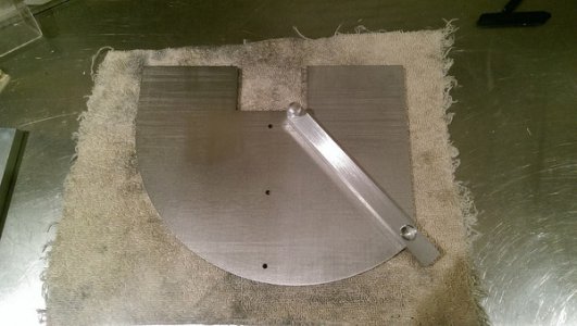
I'm talking the other edge of the straight edge. That way you are not loosing .5 to .75 of an inch of belt. another way of me saying put your 90 degree line on the edge of the belt. (see red line) Thus you still have the full use of all 2 inches of the belt. IF you put it where you show in the picture you will increase the loss of belt surface with the change of degree. The other thing would be if you could put your pivot pin for the arm as close to the corner of the belt as possible (red circle) and as close to the edge of the straight edge as possible then it seems it would give you the best use space. or at least that is what I see. Also if you create your circle for the outer rim from your pivot point then the locking system I suggestion will work better. 
")