220V, 1-Phase, SF 36 AMP Motor Trips Circuit Breaker

Gaffer

H-M Supporter - Diamond Member
H-M Lifetime Diamond Member
Joined
Sep 20, 2019
Messages
1,329
Happy Veteran's Day everyone!

I have a 7.5HP air compressor you've helped me with before. It recently began tripping the circuit breaker upon a cycle start - 135 psi I believe. If I let the air out of tank, it worked fine on initial fill cycle, but upon refill, the breaker tripped every time. The mag starter and pressure switch are new, and coincidentally the problem began soon after I replaced them. Now it trips the circuit breaker every time.

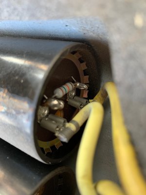
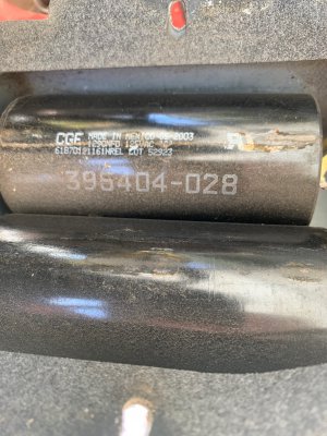
I was able to hand turn the pulley and they turn freely with negligible resistance. I removed the drive belt to isolate the pump from the motor, and it still trips the breaker. I'm hoping my problems is simply defective start capacitors. I have minimal experience with this and why I need your help. I believe the capacitor on the top of the motor is the run capacitor. There are two cylindrical capacitors on the side of the motor, and I think they are the run capacitors - and what I hope is my only problem.

I have not put my meter on them, nor tired to discharge them. From what I've read on this site, I should discharge them with resistor, and this is the part that scares me because I've only dealt with small, low voltage capacitors in the past. Note in the pictures the pair of black capacitors have resistors soldered in place from the factory.

How should I proceed? I've read that a 20k OHM, 5 watt resistor is fine for discharging, but would like an expert's opinion. I have a Fluke 87V to test them. If the capacitors are the problem, should I replace all 3 to be safe? What brand/supplier do you recommend? I don't mind spending a little more for quality, as this compressor needs to be reliable.
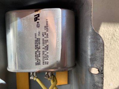
IMG_7719.jpg
IMG_7717.jpgIMG_7718.jpg
 
If it works fine when the tank is empty, I think your issue may be in the line to the tank. Generally there is a check valve, and a tiny line that goes to the pressure switch, that lets the air out of the line. It would be an easy thing to check, but compressors are different. If you could post some pics of the compressor, the pressure switch, and the line going to the tank, we could tell you how to check my theory.
 
I would replace all 3 capacitors. https://www.mcmaster.com/motor-capacitors

Use the existing resistors.

Disconnect power, let it sit for awhile, then measure the DC voltage across the capacitors to see if they have discharged. The voltage should be < 10 volts or so.

If you replace the capacitors and the breaker still trips, then maybe the start windings are damaged and the motor needs to be rewound or replaced.

I got tired of replacing 5 HP single phase motors on my compressor and bought a 3 phase motor and a single phase input rated VFD and ended the problem.
 
the problem is in the start circuit, most likely.
the start circuit has the centrifugal switch, capacitor, and the associated wiring.
you can take the cap out of the circuit and test both the capacitor and the motor.
the start switch should be normally closed until the motor is 65 to 85% of rated speed, so testing the centrifugal switch is easy
test the start windings next, there should be little resistance in the circuit, but should only have an ohm or 2
the capacitor requires an analog ohm meter to test. the test will be from pole to pole on the discharged capacitor.
when the capacitor is functioning correctly, the needle should first swing left to 0 ohms, then swing right on the dial towards infinity
it would not hurt to inspect the pressure switch contacts and associated wiring too
 
The black one is the start cap, 1290 mfd, try replacing that one first, or find someone with a capacitor meter that can test it.
-Mark
 
Another thing to check is to look in the breaker box or switch for any connections that might be loose. This condition would cause a voltage drop to the motor. Also, one of the capacitors already has what looks to be a 15,000 ohm resistor connected across it so the voltage is bled down on that one. A 20,000 ohm resistor used to bleed off the capacitors would be fine.
I would also inspect the contacts on your new pressure switch as the quality of some of this new stuff is in question.
 
No mention of the breaker size. a 7 1/2 hp 220 v motor pulls 40 amp full load (wow) I have had breaker get weak and trip like that. usually happens on applications like pumps or compressors, repeated high load starts.
 
All the wiring is new. My breaker is a standard 40 amp, and I ran 8 AWG from it to the starter, and it's a 15' run. Am I undersized? This circuit is dedicated to the compressor. All connections are tight, and all contacts are pristine. The pressure switches have been disappointing. I only replaced the original because I had to replace the starter and figured it was a good practice. The switches are the Square D brand. The first one's auto/off switch broke after about 2 months. When I put the new one in is when this problem began, though it appears coincidental - I don't know. The power input connection screws on both units were run down on both sets of contacts from the factory to a ridiculous torque - or they were glued down, but I couldn't loosen one pair, and I was barely able to use the second set. It otherwise looks and appears to function as designed.

I never had a problem with tripping the breaker before installing the present pressure switch. I confirmed the pressure relief valve worked properly, so the compressor wasn't starting under pressure at the pump. My meter will read capacitors, so I'll test them once discharged. I'm going to replace all 3 of them to be safe. I hope to have them by the weekend. I'll report back when done. Thank you.
 
Breakers have different trip curves, so for motors they are able to handle higher starting loads over short periods. Typically a D-curve. In addition a 40A breaker is too small for a 7.5Hp motor with a high starting load. In addition, if Iper NEC you are allowed to up-size the breaker for a motor load although I do not know the current specifications.

The breaker should be sized to a minimum of 125% of the motor current and should include the SFA. If the motor takes a couple of seconds to come up to speed you may have to increase the breaker size. The NEC allows up to 250% of FLA. Wire should be sized to NEC FLA values. The wire size will not match the breakers size you may be used to. I run a 5 Hp compressor with a FLA of around 26A on a 50A breaker with #8 wire, I would think you would need a minimum of a 60A breaker.
 
Thanks, mksj. I'll continue my research. In the meantime, if it helps, both of my start caps are rated at 1290 mfd. One measures 1184 and the other 1207 mfd. I'm pretty sure my run cap is fine because if the compressor started, it had no issues running to the proper psi before shutting down. It is rated at 35 mfd and measured 33 mfd. Edit: If you think these start cap values are fine, perhaps my problem is the breaker being undersized like mksj suggests. I was surprised that the owner's manual for this compressor only called for 10 AWG - but maybe that was for a 5hp motor. It doesn't specify a breaker size.

The two yellow wires that feed the starter resistor measured 2 ohms resistance. The three yellow wires to the start cap measured 2 ohms across two of the leads, and an open circuit cross two other leads. I'm not sure what I measured but was trying to follow Ulma Doctor's advice. He talked about other things in the start circuit like a centrifugal switch, but that is taking me outside my present abilities.

Edit #2: If I understand it correctly, my 36 SFA motor would have a 15-25% lower FLA rating. I found a website with a chart that says my motor should be wired with 6 AWG and have a 50A breaker. As for my starter caps, both are within 9.2% of their ratings. Is that acceptable?

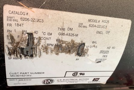
The sticker on the motor is damaged. Below is a picture of it, if it helps. Before wiring in a new subpanel and giving all my equipment dedicated circuits, my compressor shared my welder's circuit and that had a 60 amp breaker. I'm inclined to run a 6 AWG circuit and up the breaker to 50A to see what that does. Your thoughts? My who purpose for the new subpanel was to ensure all circuits were properly sized. Dang it!

Motor Tag.jpg
 
Last edited:
Back
Top