

-
Welcome back Guest! Did you know you can mentor other members here at H-M? If not, please check out our Relaunch of Hobby Machinist Mentoring Program!
You are using an out of date browser. It may not display this or other websites correctly.
You should upgrade or use an alternative browser.
You should upgrade or use an alternative browser.
220v LED
- Thread starter Aukai
- Start date
- Joined
- Mar 21, 2018
- Messages
- 1,597
Is it an AC or DC light? If it is AC, then it will have all the necessary electronics inside the package. If it is DC, then you'll have to see which terminal is "+" and which is "-".
I suspect that it is an AC indicator with the associated electronics inside.
I suspect that it is an AC indicator with the associated electronics inside.
- Joined
- Feb 13, 2017
- Messages
- 2,138
An LED is polarity sensitive, and operates at ~8-15 mA. A dropping resistor is required to limit the current to that range. On AC, the LED will light regardless of polarity because of the alternating current. It will light every half cycle appropriate to the polarity. For DC usage, polarity will need to match the supply.
In a line voltage device, 120-240 volts, the indicator is sometimes marked AC only. Sometimes a bridge rectifier is installed ahead of the LED which negates the need to align polarity. But this is a much more expensive option and usually only shows up on high end equipment. Since current is limited by the dropping resistor, the bridge can be quite small.
If the fixture is marked for voltage, use that voltage to test. Start with AC and then insert a diode (1N4002 or better) first one way then reversed to see if it is polarity sensitive. If there is no voltage listed, start with 12 volts, then 24. 24 volts is a very common control voltage for air conditioners and other domestic mechanical systems. If it doesn't light then, and only then, try 120 volts. Go to 240 only as a last resort.
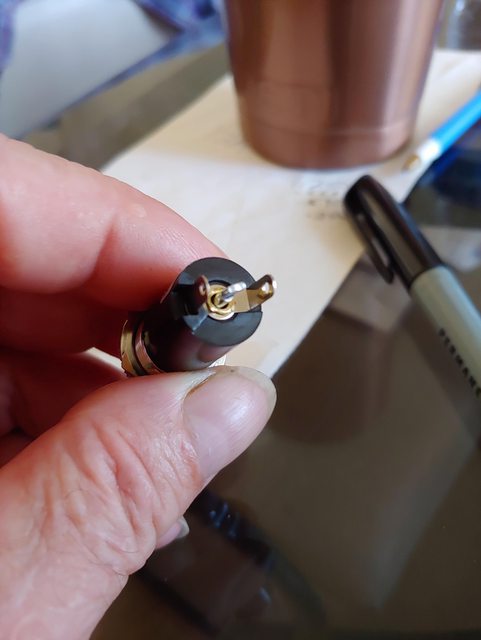
The lugs of the fixture look a little funny. When trying to determine the correct connection, the center lug is usually the line side and the brass leaves are the neutral or return. This is not guaranteed, just a general perception. Using an ohmmeter to read the brass leaves, look for zero, or near zero, resistance across them. If they are connected, they are indeed the neutral. If they are separate, you're on your own.
.
In a line voltage device, 120-240 volts, the indicator is sometimes marked AC only. Sometimes a bridge rectifier is installed ahead of the LED which negates the need to align polarity. But this is a much more expensive option and usually only shows up on high end equipment. Since current is limited by the dropping resistor, the bridge can be quite small.
If the fixture is marked for voltage, use that voltage to test. Start with AC and then insert a diode (1N4002 or better) first one way then reversed to see if it is polarity sensitive. If there is no voltage listed, start with 12 volts, then 24. 24 volts is a very common control voltage for air conditioners and other domestic mechanical systems. If it doesn't light then, and only then, try 120 volts. Go to 240 only as a last resort.
The lugs of the fixture look a little funny. When trying to determine the correct connection, the center lug is usually the line side and the brass leaves are the neutral or return. This is not guaranteed, just a general perception. Using an ohmmeter to read the brass leaves, look for zero, or near zero, resistance across them. If they are connected, they are indeed the neutral. If they are separate, you're on your own.
.
- Joined
- Jul 10, 2013
- Messages
- 1,189
For an LED light of this nature must have some internal circuits. Are there any specs or nomenclature on this item? That would help a lot.
- Joined
- Oct 4, 2016
- Messages
- 7,009
I had to run out to work, sorry I didn't put a better description. This is a 220v AC LED for the VFD cabinet, so I don't forget to turn it off. It came in a plastic bag with 0 instructions. The center pin is floating in a metal sleeve that the other terminal is attached to also, and 1 leg looks isolated.
- Joined
- Feb 1, 2015
- Messages
- 9,596
If it is a 220 volt a.c. lamp, the necessary circuitry to drop the voltage for the LED is inside. Two terminals are needed to make it work. If you have three possibles, an ohmmeter will tell you which two. As long as you don't have a short between two, you should be good the connect them to a.c.
My guess is that the two brass terminals are the correct ones.
In all likelihood, it will also light on 120v. a.c., just dimmer.
My guess is that the two brass terminals are the correct ones.
In all likelihood, it will also light on 120v. a.c., just dimmer.
Not for sure about that center terminal is for. Since it is for AC it should not mater which terminal goes to which 220 line.
You could run some tests. Use a DC supply and apply voltage to the terminals to see if it will light up a little. Start out low and crank it up. Reverse the leads if you do not see anything.
LEDs are just diodes that emit light. They do not need a bridge when AC is applied as it is already a diode. It will just light upon during one half of the 60Hz cycle. Using a bridge would mean that they first made a DC voltage and then applied that to the diode. An expense....but the light will not flicker at 60 Hz. You probably can not even see the flicker. A resistor will be in series with the LED to limit the current to a value the LED can handle. This is also true for DC LED lamps.
For example, suppose you purchase a LED lamp that they say will run on 24 VDC. It will have an LED and a resistor to limit the current. The LED voltage drop will be 2-3 volts and the drop across the resistor will be the rest of the 24 volts due to the current, V=IR. Now suppose you want to run it on 5 volts. It may run but not put out much or any light because the resistor is too large to allow much current. If you can take it apart, you can change the resistor to a smaller value to up the current and then it will be bright on even a 5 volt supply. However, mos of these things are potted so you cannot get them apart.
Have fun.
Dave
PS. In a 220 version it is possible that without some internal components besides the LED and a resistor that when the voltage is reversed accross the LED (diode) it will be too large and the diode will break down (die). However, there are Si diodes that can handle the 220 volts or higher so they may put one of these in series with the LED and the resistor. When the voltage is reverse biased accross the LED and Si diode the voltage will be mostly across the Si diode and so there will be little voltage to the LED so that it will not break down (die).
I am very curious about that center connection. It does not look familiar to me. It is possible that it is a mechanical connection. Is it possible that this thing has a switch inside? Where did you get it? Also, it is not yellow in color like the copper terminals you can solder to. Is it Al or some other kind of metal?
- Joined
- Jul 10, 2013
- Messages
- 1,189
An indicator LED usually has just two leads. There is some circuitry inside, namely a capacitor, a diode, and a resistor so that it can run on the specs for the 220v. I suspect that it is the two outer leads that you want to connect. It's that center lead that is odd.