2x72 belt grinder build

I'm certainly picture bombing this thread, but I do enjoy the ability to use a CAD model to visualize both progress and work to be done.
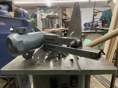
Here's my model with the parts done or in progress so far shown as solid, and the parts to be built as wireframes. Once I finish the dark green part, I'm going to have to move on to getting the base built so this thing stands decently. It is getting heavy enough to not be convenient to just move it around as needed on a table for assembly.
partially-finished.jpeg
 
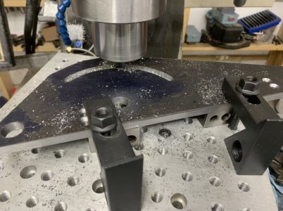
Got this part done. Cutting slots on this little rotary table is a challenge. 3/8” hot rolled, with a 3/8” wide slot using a carbide rougher. Made the slot and then smoothed out the back arc. Looking forward to having the new shop, I will then be able to use the massive 16” rotary table instead of this little 6”. The fixture plate on top is 12” x 12”.

DC461C0A-A25D-4519-B5ED-8182FF1895DF.jpeg

I debated going over it with a face mill, but it will get painted so I just sanded it to get the scale off.
B5A3E537-6324-4174-801A-553002AB61F9.jpeg

The shafts for the front rollers still need to be welded in. The 3/4” bolt/nut holding the latest part to the arm will get replaced with something a little fancier.
 
Last edited:
Next steps -
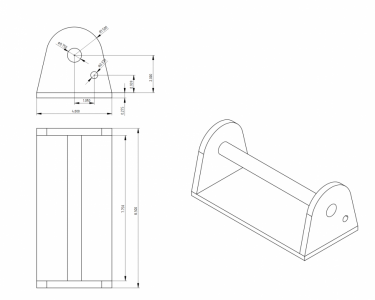
1) Build the pivoting base so I can bolt this thing down to something stable. The hole in the side (only needed on one side really) will be for a spring pin to lock the pivot in place. I may need to think about this a bit too, I doubt the pivot will see a lot of motion. The center shaft for the grinder to pivot on is 3/4" diameter. The ears on the above part are 3/8" thick, that strikes me as a fairly high pressure area and I may want to add some sort of bushing to increase the contact area to reduce wear/extend life. I'm inclined to avoid grease as it'll just hold grindings.

Some sort of bolt holes will go in the bottom of this piece:
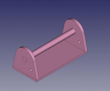
base-fc.jpegbase-fc-pdf.png


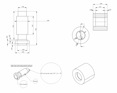
2) Build the three rollers, need two of them to mount on the front
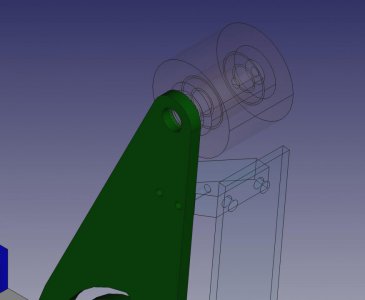
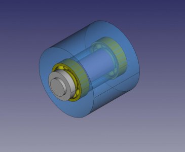
roller-mounted-fc.jpegroller-fc-pdf.png

I'm running out of 3/8" x 6 hot roll which most of this is made out of, including that pivot base. I ordered another 20' stick to be delivered in a week or so. I also need that material for the new building as bases for the bridge crane legs, so I'll use plenty of it. I'd really like another one of the Glacern 45 degree face mills, so I can keep one set up for aluminum and one for steel. Swapping inserts is tedious. But the new shop, and wiring, is going to crimp my budget for a while.

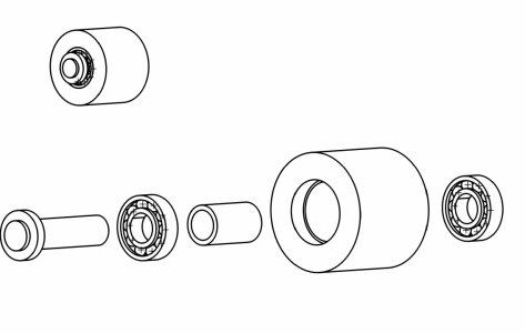
The rollers (belt wheels) are somewhat complicated in terms of parts count. And not fully illustrated. Three parts to be built, the aluminum roller, the center shaft, and the bushing. In addition there will be two R12 bearings per roller. As an artifact of learning freecad, the bushing is illustrated as an integral part of the central shaft, but will be a separate bushing/collar(?) between the bearings. Point is when the retaining bolt on he end is tightened down, pressure should go through the inner race of the bearings and through that bushing. The aluminum wheel should have just a bit (i.e., a few thou) of axial play on the bearings so that there is not an axial preload on those bearings. I think this is the right way to do this ...

The central shaft will get plug welded into the dark green arm. I'll need to fixture that pretty carefully as they need to be perpendicular to the face or the belt won't run true.

I did order a new boring bar and some ccgt32 aluminum inserts to cut those rollers, waiting on those. I can go ahead and make the wheel shaft and bushing (1018), beyond that I'm waiting on tooling and material orders.
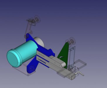
 
Last edited:
Got on the lathe to do some work on the rollers (wheels) for the belt. This is actually attempt number two :(
roller2-3d.jpeg
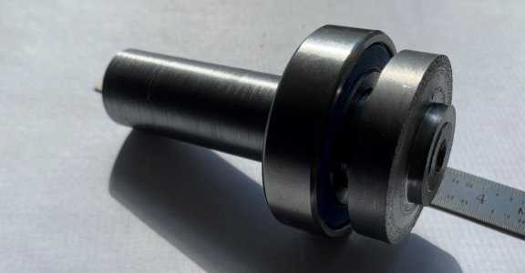
I was trying to cut these pieces out of a 4" overall piece of 1.5" dia 1018. It's shown here with one bearing on it.
IMG_4358.JPG


Here's the CAD representation of the whole thing, the picture above is just the first two parts on the lower left. I'm waiting on a new boring bar and some aluminum CCGT inserts to do the wheels.

roller2.png


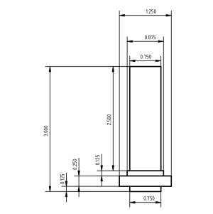
I'm really not happy with the finish on the above. I need to cut it again. Not a very complext part, although three shoulders.
roller-shaft-tc.png


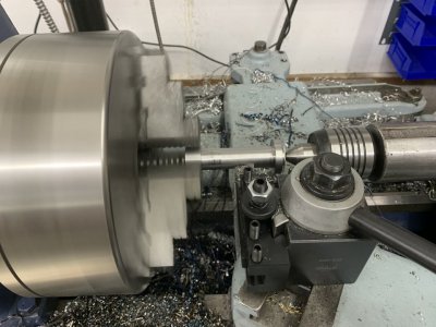
Here's the part chucked up in the lathe, almost done. Only left 1" of extra length to hold in the chuck. You can see here I'm cutting with a left hand tool, and that means I can't get right up to the chuck as I try to turn the long area down to .75" dia. Long, but the bearings ride on opposing ends of this region, so this is where hitting the numbers matter. Obviously I just need to swap to a right hand tool. I do like this Monarch CK lathe, but it is an old girl, she's been around 76 years, and the she's getting really loose in the undercarriage. This means cutting left to right vs right to left has about a 0.011 difference in cut depth diameter. This makes it difficult to finish to numbers in a area where your cutting between two shoulders, or between a shoulder and a chuck and need to swap tools. (Ok, I'm blaming the tool not the operator which is lame, but it is what it is, I'm learning). IIRC a 1.5" piece of stock will go through the spindle bore, so I'm going to try using a long blank and parting off as I go, that way I can bring the left side of the piece out another inch or so, allowing my finishing pass to be made with one tool.

Ultimately when the new shop gets done, I'll get the 612 in service and then I can go to work on putting turcite on the carriage on this one.
IMG_4356.JPG
 
Last edited:
Not a whole lot of progress. Shattered a tooth today so feeling off, not the right mindset to work around machinery. I'm waiting for some CCGT inserts to come in, bad weather today (snow on top of freezing rain) and unlikely to clear out tomorrow, so I may be waiting a while. Unfortunately the dentist office was also closed due to the bad weather, so it will be Monday before I can even get a hold of them to schedule something.

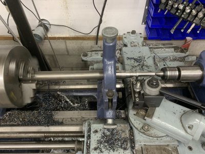
I did get a picture of the setup to cut the little axles I was struggling with above. Turns out 1.5" doesn't go through my spindle. Monarchs are not great about large spindle bores. So I had to use the steady rest.
IMG_4359.JPG
Lathe tool question, what tool works well for plunging in between shoulders? (@davidpbest ??). I tried my MSDNN with SNMG inserts, but that chatters pretty quickly, was hard to get more than a .020 cut depth in a pass. Might need a different insert. Did better stepping in alternating the left and right hand WNMG holders, but have to swap those out frequently as they don't plunge very far before the tool itself hits the stock. Thinking of trying (buying) a SCMCN tool with CCGT inserts. I did grind a 5/8" piece of HSS today into a rougher, but didn't feel up to actually putting it to the test.


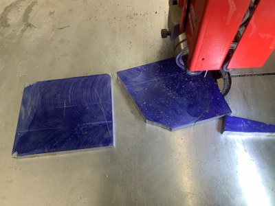
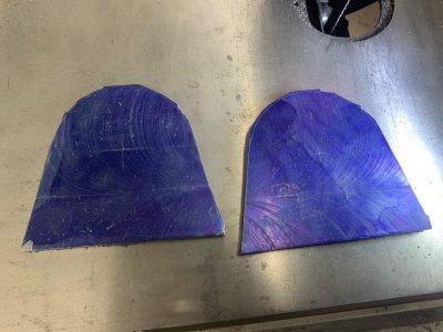
Yesterday I also bandsawed out the base for the beginnings of the pivot base shown in CAD a couple posts back. Someone earlier asked how I was roughing out the material so I'm including these pictures. My metal delivery yesterday included another 20' of 3/8" x 6" A36, so I have plenty of material to work with.
IMG_4361.JPGIMG_4362.JPG
 
Last edited:
View attachment 395007
Lathe tool question, what tool works well for plunging in between shoulders? (@davidpbest ??). I tried my MSDNN with SNMG inserts, but that chatters pretty quickly, was hard to get more than a .020 cut depth in a pass. Might need a different insert. Did better stepping in alternating the left and right hand WNMG holders, but have to swap those out frequently as they don't plunge very far before the tool itself hits the stock. Thinking of trying (buying) a SCMCN tool with CCGT inserts. I did grind a 5/8" piece of HSS today into a rougher, but didn't feel up to actually putting it to the test.
If I were machining to square shoulders on both sides, and with a steady rest involved, I would shy away from the trigon (WNMG) tooling because the insert is mounted with a negative rake and adds a significant amount of tool pressure toward the spindle centerline. My first choice would be to use a right- and left-handed tool with CNMG inserts - this will be freer cutting than the WNMG and have less tool pressure. With a neutral hand tool like your MSDNN or the SCMCN you're thinking of getting, you can't machine to a square shoulder with either of those tools, so you'd be left trying to cut the shoulders with a parting or grooving tool. Hope this helps.
 
If I were machining to square shoulders on both sides, and with a steady rest involved, I would shy away from the trigon (WNMG) tooling because the insert is mounted with a negative rake and adds a significant amount of tool pressure toward the spindle centerline. My first choice would be to use a right- and left-handed tool with CNMG inserts - this will be freer cutting than the WNMG and have less tool pressure. With a neutral hand tool like your MSDNN or the SCMCN you're thinking of getting, you can't machine to a square shoulder with either of those tools, so you'd be left trying to cut the shoulders with a parting or grooving tool. Hope this helps.
I do have the left and right cnmg tools and used them for finishing. I’m cutting a fairly short axial distance between shoulders. The problem is L/R tools have a very limited plunge depth even with multiple axial passes, before the other corner of the toolholder interferes. Was hoping to rough out a wide v groove first with the neutral tool, then finish (essentially a combination of facing and turning cuts) the shoulders with the cnmg. Should be able to do that without needing to repeated swap between left and right tools. Just a matter of reducing tool changes.

Note that while I say plunge and v groove, I’m still doing some component of axial (turning) cuts. I was surprised how little I could plunge the snmg radially, only about .010 DOC (.020 off the diameter) before needing an axial pass or it chattered. I may need to investigate my snmg inserts. After reading your book I have moved to name brand inserts but now I’m wondering if those are some older off-brand left-overs. But I was hoping a ground edge insert (ccgt) would do a bit better than a molded edge snmg.
 
Last edited:
I do have the left and right cnmg tools and used them for finishing. I’m cutting a fairly short axial distance between shoulders. The problem is L/R tools have a very limited plunge depth even with multiple axial passes, before the other corner of the toolholder interferes. Was hoping to rough out a wide v groove first with the neutral tool, then finish (essentially a combination of facing and turning cuts) the shoulders with the cnmg. Should be able to do that without needing to repeated swap between left and right tools. Just a matter of reducing tool changes.

Note that while I say plunge and v groove, I’m still doing some component of axial (turning) cuts. I was surprised how little I could plunge the snmg radially, only about .010 DOC (.020 off the diameter) before needing an axial pass or it chattered. I may need to investigate my snmg inserts. After reading your book I have moved to name brand inserts but now I’m wondering if those are some older off-brand left-overs. But I was hoping a ground edge insert (ccgt) would do a bit better than a molded edge snmg.
Sorry, I misunderstood that "plunge depth" was your chief concern. The turning/facing tools are not optimized around maximizing plunge depth. If you want a more significant plunge depth, I would be selecting a rigid grooving tool such as a Kennametal Top Notch. This version will plunge to 0.125" and if you equip it with a full radius insert (like this) you can plunge in and move the tool laterally. The same tool can be used for threading and parting-off to 0.150" depth. See p70-72 in my book. You'd need to clean up the square shoulders once finished using a right- and left-handed CCMT tool, or a parting blade.
 
Sorry, I misunderstood that "plunge depth" was your chief concern. The turning/facing tools are not optimized around maximizing plunge depth. If you want a more significant plunge depth, I would be selecting a rigid grooving tool such as a Kennametal Top Notch. This version will plunge to 0.125" and if you equip it with a full radius insert (like this) you can plunge in and move the tool laterally. The same tool can be used for threading and parting-off to 0.150" depth. See p70-72 in my book. You'd need to clean up the square shoulders once finished using a right- and left-handed CCMT tool, or a parting blade.
Thanks David, I'll look into that. It would have made that operation a lot simpler.
 
Last edited:
Back
Top