2x72 belt grinder build

Randal, I don't have any experience with the Iscar Top Notch inserts, but see no reason why they wouldn't be an excellent choice. Dorian also makes inserts in this style under the brand name Dor Notch - sometimes you can find them on eBay. That said, I don't immediately see how you'd employ that boring bar for the shouldered operation you were asking about a while back. Also, keep in mind, that the size 3 Top Notch inserts are available with a variety of threading profiles (including Acme) in case you need to do some serious internal threading.
I’m planning on buying a right hand top notch tool. The only reason the boring bar is relevant is that it is a size 3 so I’ll buy the size 3 right hand tool for insert compatibility. Thanks for taking the time to respond to all of the queries, much appreciated.
 
I’m planning on buying a right hand top notch tool. The only reason the boring bar is relevant is that it is a size 3 so I’ll buy the size 3 right hand tool for insert compatibility. Thanks for taking the time to respond to all of the queries, much appreciated.
This is the version I have, and I like it very much. Very rigid setup with that and the size 3 inserts are very robust.
 
Daily photobomb

I made another shaft to replace the one with the less than satisfactory finish. Of course it is the last one I need, but I finally got the setup on the lathe in a way that made it relatively easy to cut, using the tools I have on hand. Thanks to @woodchucker, @WobblyHand and @jwmay's suggestions, I did use a parting tool to turn about 1/4" of the shaft. This was certainly more feasible in my mind than turning a whole 2.5" that I was struggling with in the above config with the tailstock and steady rest.

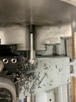
I chucked up a roughly 7" piece of 1.5" dia 1018 in the chuck, with about 4" sticking out, to make a 3" finished part. I cut the right hand side with a RH WNMG tool, up to the large shoulder. I used that same tool to turn the large shoulder and about 1" beyond it to finished size (1.25").
Then I used a parting blade to bring about .30" beyond the large shoulder down to .750" (finished size). I did that as a combination of multiple plunges, and then some turning at about .005" cut to get it down to size.

The problem with that approach is that I ended up with left side of the shoulder a bit tapered rather than a 90 degree face. That face is critical as it registers against the base plate to keep the shaft square when welded in, so it needs to be a clean 90 face. I tried a couple time to plunge the parting tool in, or turn up to the shoulder, right on dimension, but I could see the parting tool start to bend off to the left. So I used a left hand hss 1/4" facing tool to fix that shoulder, then back to the parting tool to actually part it.
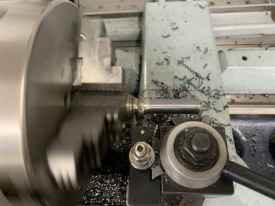
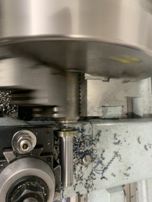
IMG_4387.JPGIMG_4388.JPG

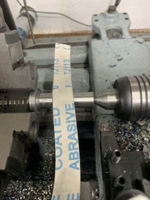
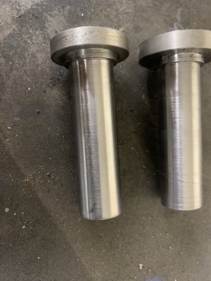
Then I flipped it around and cleaned up the parted face with CNMG tool. Note that there was a bit of runout on the part, but just facing the end off that isn't critical. It did make the deburring chamfers a little sloppy. Then I flipped it back to sand the part to a final bearing fit. For anything other than the initial chuck configuration, these where barely tightened in the chuck to prevent damage. For the sanding pass I put the tailstock in the 3/8" bolt hole that had already been drilled and tapped in the initial setup. Note sure you can tell the difference in the picture, but the finished and fit on the one on the left works (this last setup), the bad one is on the right.

Anyway, it was an interesting combination of working with both carbide and HSS that made this work, two of each. Certainly it could have been done with all of one or the other. In this case it worked out quite well to mix them, the carbide inserts allowed me to quickly get from 1.5" to .75" over a 2.5" length, while the HSS allowed me to get into the narrow working area without extending the stock out farther and using more stock to work into that shoulder. Certainly it could have been done with either all HSS or all inserts, but this worked best for me.

I think there is a lot of skill and experience to getting a feel for what you can do with each type of tool, so that you can come up with good setups. Cutting flipped parts always creates questions of runout, a 4 jaw chuck can minimize those, but in this case I cut all of the critical surfaces in the same setup, which regardless of the chuck type, gives you the minimum issues with runout.
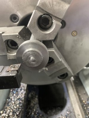
IMG_4389.JPGIMG_4390.JPG
IMG_4391.JPGIMG_4392.JPG

I wanted to make sure these shafts were set perpendicular to the plate. I believe this will be critical to belt tracking.
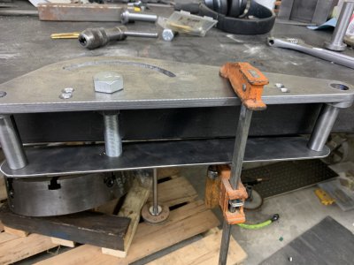
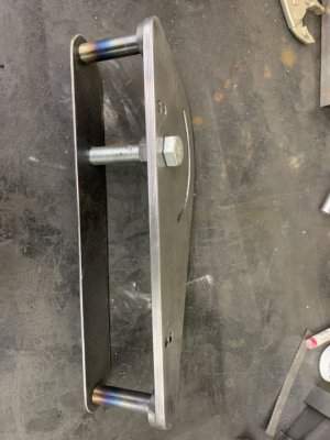
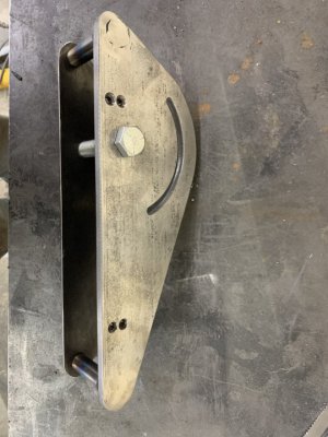
Bolting these to the plate would allow that. But I was sort of set on welding it. Bolt heads would create a clearance issue with the support arm, flat head screws with counter sunk bolts would solve that. But in my mind there is some merit in learning to combine machining with welding, and to explore the limits of that. Obviously the problem is welding risks heat and cooling contraction pulling the shafts out of square. The large shoulders and plug welds help to alleviate that, but help is not "gaurantee". I made up a 1/8" x 2" piece of flat (rectangular) stock to support the ends of the shafts, and reference the 3/4" pivot bolt. I pressed the shafts into the plate and then clamped it to the bench and welded it up.
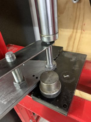
IMG_4393.JPGIMG_4394.JPG


I used the TIG welder to start the plug welds, first to just tack them and check square, but that was really pushing the top end of my TIG welder and going slow. So after getting a good root around the perimeter of the plug with the TIG, I filled it in with the MIG. Here's some pictures after grinder the welds clean. You can see a bit of undercut on the top of the second picture, so it wouldn't pass a weld inspection but I doubt it'll be an issue here. I left this cooling, I'll make up the other aluminum wheel and assemble this with wheels on the arm next.
IMG_4395.JPGIMG_4396.JPG
 
Last edited:
Fwiw, my intuition is that the shafts need to be squared to within some fraction of the angle of crown I put on the wheels. I don’t know if that fraction is 1/2, 1/10 or I’m totally off base?

I plan to use the compound to put a 1 degree taper on the outer 1/3 of each wheel as a starting point. Trail and error may apply.
 

Hall of shame​

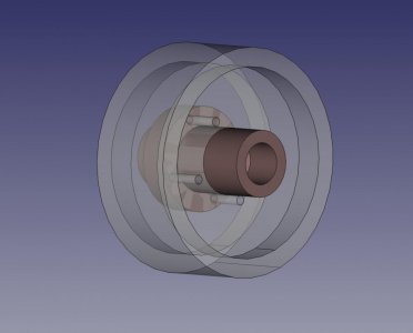
I have been working on the hub for the motor, the brownish part in the CAD picture below. Want to get this true, so the drive pulley runs well.

drive-pulley.jpeg

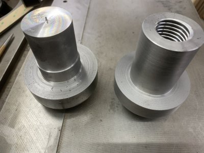
I decided to make in out of 12L14, having never used it before but figured now was a good chance (first mistake). It does cut nice, but it cuts a LOT different than 1018 or A36 that I often work with, much more like aluminum. I found that my aluminum insert tools worked a lot better than the ones for general purpose steel. (Both are ISCAR inserts, good quality).

Normally when I'm cutting something down to size, I'll touch off and set my dails so that "0" is the final cut dimension, at least a close estimate. For example, this was a 3" diameter piece and I was turning down to 1.750, so 1.250 to remove off the diameter. My dials are .500 per revolution, so in this case I'd set .250 after touch off. After switching from steel to aluminum inserts (different tool), I didn't measure and reset my dials. So I blew right pass my dimensions. You can see on the left piece where I had a sudden DUH moment and stopped the cut, but I'd already blown the piece.

I tried again over the weekend, had been waiting to get a .875 reamer. Got the main body turned down to 1.750, hit the number so the larger (gray) aluminum wheel fit on there perfectly (a snug slip fit). Got that done on Saturday and left it chucked. Yesterday was not an ideal day, horse colic'ed and had to tube him twice, always a pain and sometimes a struggle even with a bit of tranquilizer. I hate to use too much of that in cold weather as it messes with their temperature regulation. Was also trying to get the several other things done for the new building, etc. Probably too scattered to work in the shop. But I went ahead and drilled and reamed the center hole to .875, then threaded it at 1.125 x 8TPI. Threading went really well even if it took a while to cut that large thread. It's a total of .162 ID cut (or .081 thread depth) for 75% thread, and I did it at .005 cut increments.

I had done all of that without unchucking the part to try for concentricity. But when I pulled the part off and tried the fit on the motor, it was sloppy. Way too sloppy to be usable. Sigh. Either my reamer is off size, or more likely the toolpost wasn't square or the drill wondered. I had wanted to ream it as the total hole depth is 3.75 on a .875 hole, so a bit of a stretch for steel boring bars, don't have any carbide bars.

I suppose I could chuck it up in the 4 jaw, indicate it in, and bore it out for a press bushing. But I ordered 1' of 12L14, so I'll try one more time and keep the bushing option as plan B

.IMG_4420.JPG
 
Man, Sounds like a hell of a weekend. I hope your horse is doing better today. Bummer about the flop on the hub.

Looking forward to round two.

Tim
 
I'm going to have to thread a chuck soon. Heard it said it is wise to make a copy of the thread you are matching to. Said to help avoid surprises. I'm going to make a copy of my spindle, just for this reason.

Don't understand why you reamed out the screw hole in the beginning. Shouldn't it be good enough to thread if bored? 0.875" is under the minimum minor diameter of a Class 2 internal thread. According to my copy of Machinery's Handbook, the min minor diameter for 1.125-8 is 0.9897" and the max minor is 1.0045".

Is this hole threaded all the way through?
 
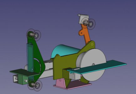
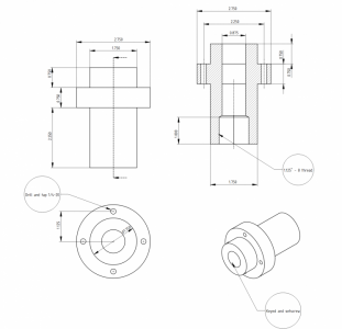
@WobblyHand - good question, here's the CAD drawings of the part. One end is intended to go over the keyed .875 motor shaft. The other end is threaded to accommodate attaching a disc for the disc sander option. Not sure I'll even finish that out, but I'm building it to allow for that. Since both parts are shop made if I do finish out the disc, a disc would be cut to fit this hub. I didn't consult the handbook, just figured 8 TPI is .125". The height of an equalateral triangle is sqrt(3)/2 times the base. Took 2x that for threading both sides, then 75% thread engagement. Came up with .963 bore IIRC. Notes are in the shop. Since I have to redo it, I'll probably check the Machinery Handbook and try for a proper 1.125x8 thread.
grinder2.jpghub.png
 
I'm guessing that the .875 diameter is to mount on the motor shaft. Keyway and setscrew(s) unknown at this time.

Also guessing, the 1.125-8 thread is the mount for sanding disc (separate feature from the .875 diameter).

I previously noticed a sign that referred to horses, but the previous post was the first time I've read you mention any. You're a busy guy.

Edit: LOL, typing simultaneously.
 
@rabler

I see the drawing of the hub says "keyway and setscrew". How do you propose to create the keyway.
 
Back
Top