3 Phase Delta WYE Resistances

Scra99tch

H-M Supporter - Sustaining Member
H-M Platinum Supporter
Joined
Dec 2, 2016
Messages
234
So the motor connection I have is 6 lead.

U1 V1 W1

U2 V2 W2

If I measure across from U1 to W2 I get 71.9 Ohms
from V1 to U2 I get 128 Ohms
from W1 to V2 I get 71.9 Ohms

If I measure from U1 to U2 I get 71.8, from V1 to V2 I get 71.9 from W1 to W2 I get 128.2

This I take it means it is wired for both. If I want high speed I bridge U1,V1,W1 with line in for WYE or star winding.

My question is why the higher resistance on one of the windings should they not all be the same.

Thanks
 
They should be the same, there may be a problem. Hard to say what it is, if there was a short in one winding you would expect one winding low and the other two high.
Have you measured them to ground? (the case)
-Mark
 
Yup all are open to ground. NO resistance on any leads to the case. Which is I good sign.

I am just wondering being a two speed motor could they have wound the wires a few more loops on one of the windings or used a different smaller gauge?

Have not read anywhere to be the case, that different gauge wires are used in windings.
 
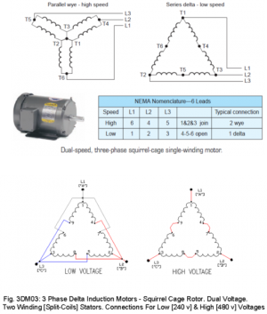
Here's a diagram of a typical 3-phase unit- no matter how you measure it it should be equal on all three sides
So looking at the series delta- low speed diagram I'm thinking that one of the six junction points is open: T1 thru T6 Just a guess
Try measuring U1 to U2, then V1 to V2, then W1 to W2 see what you get


1606237802910.png
 
Last edited:
Seems to be something fishy with the W1 to W2. See if wiggling the wires changes the reading. I guess the next step would be to open up the motor.
There may be a flaky solder joint
 
So it is a two winding motor. Measuring across UaVa, VaWa and UaWa I get equal(ish) ohm readings, tying UaVaWa together and measuring UbVb, VbWb, and UbWb I get another set of equal(ish) readings.

Motor is good, I confirmed by supplying line voltage to each setup and strobe'd the pulley speed which is close to printed speed. I checked the current draw with my amp meter and both speeds pull stated amperage.


Now for the hard part, anyone want to take a stab at my Dahlander switching problem??
 
I've posted to numerous places so maybe not in here yet.

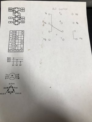
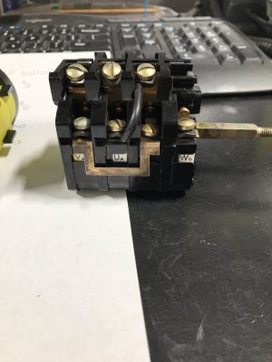
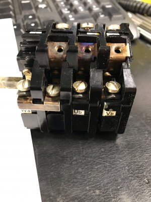
The old switch was a Siemens switch made out of bakelight and it crapped the bed causing one of the cams not not function. I was not able to get the cam position initially when I pulled it apart.

I bought a new dahlander switch and when hooked up to the above configuration on position 1 of the switch which would be 123 (UaVaWa of motor leads) contacted to RST. The will motor hum and will trip the breaker in both low and high speed position. I can send a picture of the new switch also if need be. But the picture below is the wiring diagram for the new switch as you can see there is 4-5 places where terminals are shorted. On the old switch there are 3 terminals which are shorted.


image0.jpegimage6.jpegimage5.jpeg
 
Last edited:
Back
Top