- Joined
- Feb 2, 2013
- Messages
- 3,625
Hi everyone,
I finally got my Burke #2 back together and was going to setup an RPC to run the gear motor on it.
When I purchased the burke, the seller threw in another 3 phase telling me that I could build a RPC from it. (did a google search on how to wire)
I wanted to test the whole RPC setup and figure out what size run capacitors I would need..
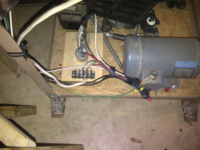
I hooked up the extra motor as follows:
L1 (as indicated on the wire) -- 1 leg of the 220 Circuit out of the wall and to 2 capacitors wired in parallel, 40 mf and 15 mf (I bought a whole assortment as I wasnt sure what i needed).
L2 -- 2nd leg of the 220 circuit out of the wall
L3 -- to a momentary switch which then goes to the other side of the caps.
ground to the frame of the motor.
turned off the circuit breaker, plugged the wire in.. turned on the circuit breaker expecting to have to hit the switch to get it started.. low and behold the motor started spinning w/o me touching the switch (i checked the switch to make sure it was infinite resistance as is and 0 resistance when the button was pressed).
thought maybe the caps were in the circuit somehow so I pulled the wires to take them out of the circuit completely.. the motor still starts??
questions:
1. is it possible this was converted to 1 phase (i doubt it since the wires say l1, l2, and l3)?
2. it the motor going to burn out ( i only ran a few seconds each try since I was not expecting this)? if so what should I be looking at/testing?
3. if not, do i still need start (and run capacitors)?
thank you,
Roger
some info on the label of the motor:
Rockwell 1 hp motor, manufactured by baldor. 1725 rpm, 4.4 amps, 3 phase. rockwell no 66-018
View attachment 36500
Roger what has happened to you when you fired the motor off with your original configuration, you were creating the potential difference to start the motor, if you were using start capacitors they would burn up very quickly the way they were wired in.
a static or rpc starts the motor in single phase, boosting the third leg with a discharge of the start capacitor. once running the intended motor whether it's an idler or a mill/ drill press or any other type of 3 phase motor, the third leg will be induced , provided that there is a single phase of sufficient power being supplied uninterrupted.
once your 3 phase motor starts, there is no need for the starting capacitor. it is taken out of the motor circuit by a momentary switch . if you are starting a idler motor the idler will produce three phase power being started on single phase power, then after generating the third leg, can start multiple motors on three phase power.
you will need at least a start capacitor to start the idler motor
if you wish to balance the voltage between phases you will add run capacitors
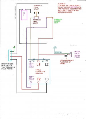
your start capacitor should be greater than 80 microfarads for a 1 hp motor, put that in series with any 1 lead 1,2, or 3, with the normally open momentary switch, then connect 1 hot leg (i.e. red) to 2, then the other hot leg(i.e. black) to line 3.
you will make a jumper wire from either 2 or 3 to the start capacitor, this will go to the common side of your star capacitor to power
i made a diagram in an earlier post here it is, this will start you motor without question.

[video=youtube;xD8xwh_P8mI]http://www.youtube.com/watch?v=xD8xwh_P8mI[/video]
let me know if it helps u out!


