

-
Welcome back Guest! Did you know you can mentor other members here at H-M? If not, please check out our Relaunch of Hobby Machinist Mentoring Program!
You are using an out of date browser. It may not display this or other websites correctly.
You should upgrade or use an alternative browser.
You should upgrade or use an alternative browser.
3D print graduated dials and rings!
- Thread starter Technical Ted
- Start date
- Joined
- Nov 5, 2016
- Messages
- 1,419
I am gobsmacked by how crisp the features are. Did the ring sit flat on the platen and the nozzle laid down that detail at the edge of the print?
I'd like to see how the actual print of Mike's turned out since he used PTEG and I used PLA. As you probably know, PETG is a lot stringier than PLA. Since there's no heat or sunlight involved, I used PLA because it's a little stiffer and typically prints a little "cleaner".
I printed mine with the division lines down on the smooth surface of my smooth print sheet. As posted earlier, my printer is a Prusa Mk3S+ and I used PrusaSlicer.
Mike, do you have a picture of your finished product?
Ted
- Joined
- Nov 25, 2015
- Messages
- 8,235
That's not the results.... That's the beginnings... A pic of the dial ... inquiring minds want to see the finished product..Technical Ted, similar to you I used Fusion 360 to design a larger dial for one of my Logan lathes and printed it on a Prusa MK3S in PTEG plastic using the Prusa Slicer. Happy with the results.
")
- Joined
- Dec 14, 2013
- Messages
- 167
If woodchucker is referring to me, here it is:
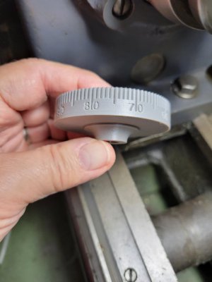
Here's a picture of the crossfeed dial printed out in PETG. The dial was printed with the side where my index finger is facing down on on the build plate. Used Prusa Slicer at .2 layers with a .4 nozzle.
I just need to make a sleeve with an index line and lock screw to slide over the crossfeed screw base which I haven't gotten around to it yet and install he new dial and base on the lathe. I think, for me, the hard part is over on this part which is designing the dial in Fusion 360.
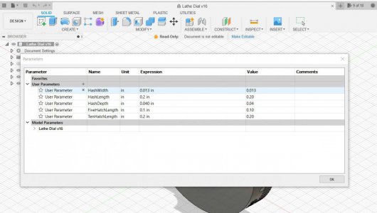
Addressing parametrics, Fusion 360 incorparates a table of change values where you name the variable and put in a number , like a spreadsheet, and the value can be input direct or calculated from other input numbers or named variables. You can get as basic or as complicated as you want. I included a picture of the values that I used to make the hash mark lengths on the dial. The numbers were put into the 3D model manually so I could play with the lengths by plugging different values in to change the model until it looked right. The 1, 5, and 10 thousandth hashes are different lengths as you can see in the picture. Parametrics could have been used to dimension the dial size and thickness as well but for some reason I just put those dimensions directly into the drawing.
Was happy when the 3D model and 3D print was done because it gave me a headache.
Hope this helps.
Best regards.
Here's a picture of the crossfeed dial printed out in PETG. The dial was printed with the side where my index finger is facing down on on the build plate. Used Prusa Slicer at .2 layers with a .4 nozzle.
I just need to make a sleeve with an index line and lock screw to slide over the crossfeed screw base which I haven't gotten around to it yet and install he new dial and base on the lathe. I think, for me, the hard part is over on this part which is designing the dial in Fusion 360.
Addressing parametrics, Fusion 360 incorparates a table of change values where you name the variable and put in a number , like a spreadsheet, and the value can be input direct or calculated from other input numbers or named variables. You can get as basic or as complicated as you want. I included a picture of the values that I used to make the hash mark lengths on the dial. The numbers were put into the 3D model manually so I could play with the lengths by plugging different values in to change the model until it looked right. The 1, 5, and 10 thousandth hashes are different lengths as you can see in the picture. Parametrics could have been used to dimension the dial size and thickness as well but for some reason I just put those dimensions directly into the drawing.
Was happy when the 3D model and 3D print was done because it gave me a headache.
Hope this helps.
Best regards.
Attachments
Last edited:
- Joined
- Dec 14, 2013
- Messages
- 167
I was able to export the Fusion 360 model of the dial which is in an F3D file format if anyone wants it to play with. If so, PM me.