- Joined
- Feb 2, 2014
- Messages
- 1,056
I did not plan on building this engine as it is designed for an RC airplane and I never got into that hobby. It not something you can just set on the counter and start it up for a while to watch it run like I do with my other engines. It is recommended to use at least a 20" propeller and produces some serious horse power.
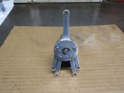
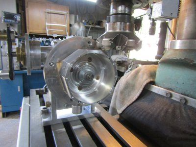
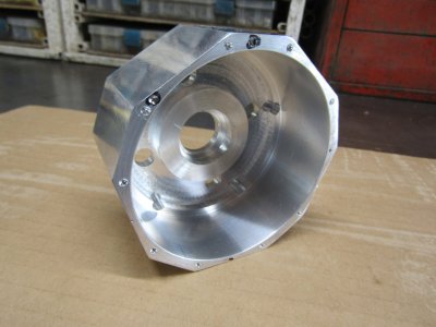
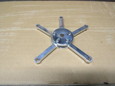
I ran across a set of plans for an Edwards 5 radial engine and was just looking through the pages when the master rod drawing caught my eye. It looked like an interesting part and I thought I will make just the rod for a conversation piece that's all. Well it turned out very nice almost excellent but it didn't demonstrate how the other rods were connected and the path that they followed.
The other four rods were all identical and a rather easy build so I decided to make them but now I had to make the link pins to hold the rods on. Well the link pins are held in position by the link pin retainer plate that captures the pins and hold everything together. Not exactly there is a C clip that holds the retainer plate in place but that clips on to the crank pin that is pressed into the crank shaft arm and there is a needle bearing in the master rod to match the crank pin. I might as well make the crankshaft too so I can attach the crank pin to something and really demonstrate how a radial engine works.
So now you see how all this got started and just keeps going.
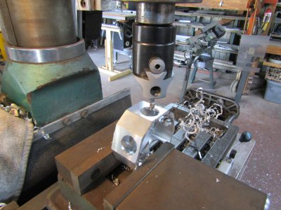
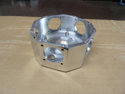
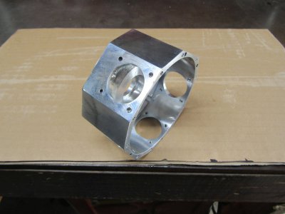
I have now decided to try my hand at building this complex model engine and I will give it my best shot.
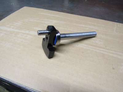
The crank shaft also has a counter weight that bolts onto the crank throw.
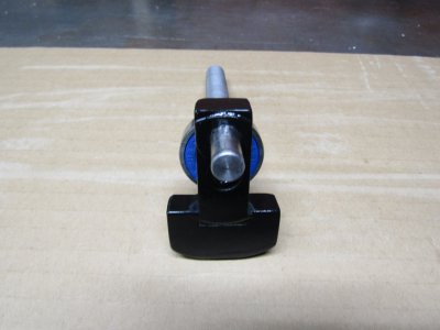
I will be following the plans closely but I will be using the materials I have on hand as much as possible.
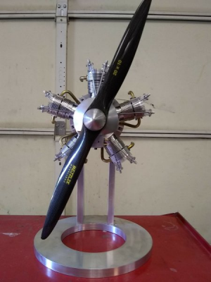
This is an example of the engine. I hope mine looks half as good.
Thanks for looking
Ray
I ran across a set of plans for an Edwards 5 radial engine and was just looking through the pages when the master rod drawing caught my eye. It looked like an interesting part and I thought I will make just the rod for a conversation piece that's all. Well it turned out very nice almost excellent but it didn't demonstrate how the other rods were connected and the path that they followed.
The other four rods were all identical and a rather easy build so I decided to make them but now I had to make the link pins to hold the rods on. Well the link pins are held in position by the link pin retainer plate that captures the pins and hold everything together. Not exactly there is a C clip that holds the retainer plate in place but that clips on to the crank pin that is pressed into the crank shaft arm and there is a needle bearing in the master rod to match the crank pin. I might as well make the crankshaft too so I can attach the crank pin to something and really demonstrate how a radial engine works.
So now you see how all this got started and just keeps going.

I have now decided to try my hand at building this complex model engine and I will give it my best shot.

The crank shaft also has a counter weight that bolts onto the crank throw.

I will be following the plans closely but I will be using the materials I have on hand as much as possible.
This is an example of the engine. I hope mine looks half as good.

Thanks for looking
Ray


